3
\$\begingroup\$

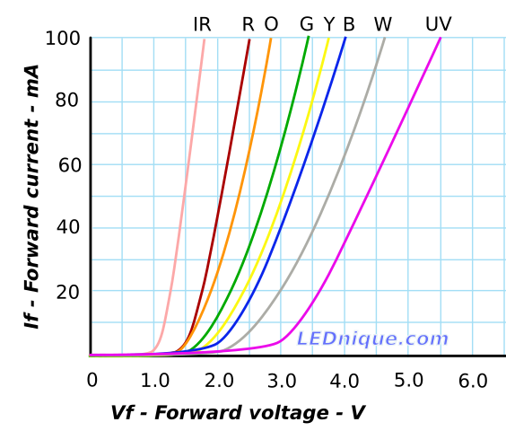
I know that if an LEDs are to be connected in a parallel circuit, a resistor must be added to limit the current rate flowing through them. But let's assume that I have blue LEDs with rated forward current of 40 mA and these are connected parallel to 3V power supply. IV curvature shows that for 40 mA it is required forward voltage of 3V, which means that in such a case there is no need for additional resistors, right?

Typical IV curves for various colours of LEDs.

Source: LEDnique - IV curves

Also, if LED have nearly zero resistance, then in case if we add resistor in series with an LED, there will be no voltage drop across LED (all voltage will drop across resistor). As result you cannot reach voltage drop across LED that is greater than forward voltage and current won't flow through it, isn't it so?

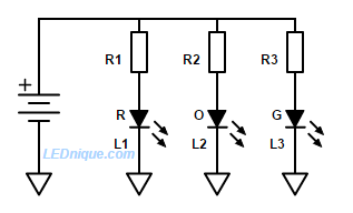
For low-voltage applications a single resistor per LED prevents current hogging by the LED with the lowest Vf

Source: LEDnique - Parallel LEDs – the problem

\$\endgroup\$
6
  • \$\begingroup\$ In theory nobody can stop you from omitting the current limiting resistors if you have a voltage source that is precise enough to be set at the output current of 40mA that you measure from the graph. However bear in mind that optical output of a LED varies quite allot with current, and from diode to diode there is variation. You could end up with LEDs from different manufactured batches with large differences in the optical and V-I characteristics, enough so that you could visibly see one LED brighter than another... \$\endgroup\$
    – citizen
    Sep 18 at 11:46
  • \$\begingroup\$ Additionally adding a larger resistance (say 330 Ohms), than that of the internal LED resistance (in its active state maybe a few Ohms) removes some of the natural variations in internal LED resistance, from one diode to another diode (again due to manufacturing tolerances), and this provides a more constant current. Don't forget, it's the bias current that sets the optical output power of a photo-diode and it's this you want to keep at a known value across all LEDs ... much harder to achieve when LEDs are in parallel, and worse if you don't provide a bias resistance ... \$\endgroup\$
    – citizen
    Sep 18 at 11:52
  • 1
    \$\begingroup\$ "no voltage drop across LED (all voltage will drop across resistor)" is a fundamental misunderstanding of what happens when you mix passive and active components. The voltage drop across a resistor is given by Ohm's Law. There is no voltage-divider law. The voltage-divider calculation comes from Kirchoff's Laws applied to two resistors, both obeying Ohm's Law. The LED isn't covered by Ohm's Law. \$\endgroup\$
    – Ben Voigt
    Sep 18 at 20:54
  • 2
    \$\begingroup\$ Tomass Ozoliņš - Hi, Please note the site rule which requires that when a post includes content (e.g. text, image, photo etc.) copied or adapted from elsewhere, that content must be correctly referenced. As a minimum, for online material the source webpage or PDF etc. should be linked (see that rule regarding references for books / articles etc.). In order to help you, I found what I believe to be the source webpage links & added them. For the future, please remember it's your responsibility to do that :) Thanks. \$\endgroup\$
    – SamGibson
    Sep 18 at 21:27
  • 1
    \$\begingroup\$ @SamGibson Thanks! :) \$\endgroup\$ Sep 19 at 17:50

1 Answer 1

2
\$\begingroup\$

IV curvature shows that for 40 mA it is required forward voltage of 3V, which means that in such a case there is no need for additional resistors, right?

That is correct, but temperature changes or manufacturing tolerances cause that curve to differ and the curve is steep. So a small increase in ambient temperature would cause more current -> more internal heating -> ...

Also, if LED have nearly zero resistance, then in case if we add resistor in series with an LED, there will be no voltage drop across LED (all voltage will drop across resistor). As result you cannot reach voltage drop across LED that is greater than forward voltage and current won't flow through it, isn't it so?
LED does have a voltage drop, but the drop doesn't behave as a resistive load. Part of the behaviour can be considered as a resistance. Particularly the linear part of the IV curve.

So you need to pick a value to on the IV curve, use that as the voltage drop, size the external resistor and as a result you'll be somewhere near to what you wanted, but temperature change and manufacturing tolerances didn't let you hit the mark exactly.

If there was no voltage, there would be no power, so the LED couldn't radiate any energy (light up).

\$\endgroup\$

Your Answer

By clicking “Post Your Answer”, you agree to our terms of service and acknowledge that you have read and understand our privacy policy and code of conduct.

Not the answer you're looking for? Browse other questions tagged or ask your own question.