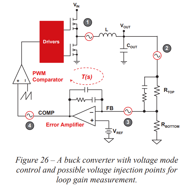
I have come across this document https://www.ti.com/seclit/ml/slup386/slup386.pdf , where injection points for stability measurement are discussed in Fig.26.

For point 3 it says: "Because the op amp has negative feedback, the inverting input of the op amp is virtually the same as the positive input, which is a DC reference voltage, VREF. VREF appears as an AC short, making the equivalent impedance looking forward almost zero."
I suppose (but am not sure) the "negative feedback" mentioned here is the local feedback of the error amplifier, i.e. just the compensation components. This is what makes the input impedance error amplifier almost zero, not the global feedback that includes everything (PWM comparator, drivers, filter,...).
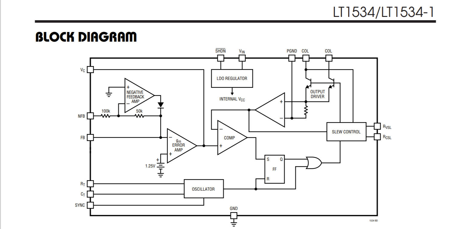
If this is true, could an injection point between the resistor divider and the FB pin be valid if the error amplifier was not an operational amplifier but an OTA, which has no local feedback (compensation components from output to ground)? And in the special case of LT1534 https://www.analog.com/media/en/technical-documentation/data-sheets/1534fa.pdf with its negative feedback amp: even with NFB pin disconnected, the negative feedback amp and its output diode would make the impedance looking into the FB pin either very small or very large and the injection point at FB would not be valid, correct? And even buffering the divider with an operational amplifier would not make its impedance much smaller than the impedance looking into the FB pin of LT1534.
EDIT: I overlooked the fact that for the LT1534 the negative feedback amp's output diode will be closed when Vfb = 1.25V, rendering the negative feedback amp irrelevant wrt impedance looking into the FB pin.
So my main question is: is the OTA's input impedance high because it has no local feedback (unlike an op amp, which has a local feedback via its compensation components)?

