Electret mics supposedly use current of 0.5mA to 1.5 mA. In all JFETs the current at VGS = 0V is around 10mA. What JFET is then used in electret mics to be able to be powered by a laptop for example at 0.5mA ?
-
1\$\begingroup\$ just about any JFET made from silicon would do. \$\endgroup\$– Marcus MüllerCommented Sep 22, 2023 at 22:24
-
\$\begingroup\$ The JFE150 would be a good example. It will work quite well at \$500\:\mu\text{A}\$. \$\endgroup\$– periblepsisCommented Sep 22, 2023 at 22:24
-
\$\begingroup\$ The ancient BF852 might be another option to consider. I haven't looked around to see if they still can be had, though. And I don't know what device is used in any particular electret. \$\endgroup\$– periblepsisCommented Sep 22, 2023 at 22:50
-
\$\begingroup\$ Neither is it true that all JFET have 10 mA IDSS, nor would a lower IDSS of ~1 mA be required to make it work. You can always reduce the quiescent operating IDS below the value of IDSS, by adding a source resistor. The source resistor also makes the amplifier more linear. \$\endgroup\$– tobaltCommented Nov 17, 2023 at 5:13
2 Answers
Unfortunately, low-current JFETs are becoming extinct, probably due to the advent of MEMS microphones. FJX597 (obsolete), TF256 (obsolete) and the TF412 (still available) are JFETs I have used for <1mA preamps.
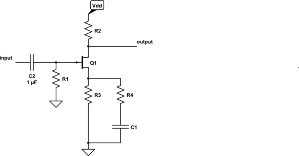
You typically wouldn't be using a VGS = 0 if you use a source resistor. Adjust the source resistor value to the desired drain current. You can use load lines to figure out the value just like the old vacuum tube days, or, figure this out empirically (use a variable resistor in place of R3).

simulate this circuit – Schematic created using CircuitLab
R1, gate bias resistor, can be some high valued resistor, perhaps 1 MEG.
R3 is used to set the drain current.
If using as an amplifier, you'll probably need R4 & C1 to set the gain along with R2.
If making a source follower (gain slightly less than one), get rid of R2, R4, and C1.
[Edit]
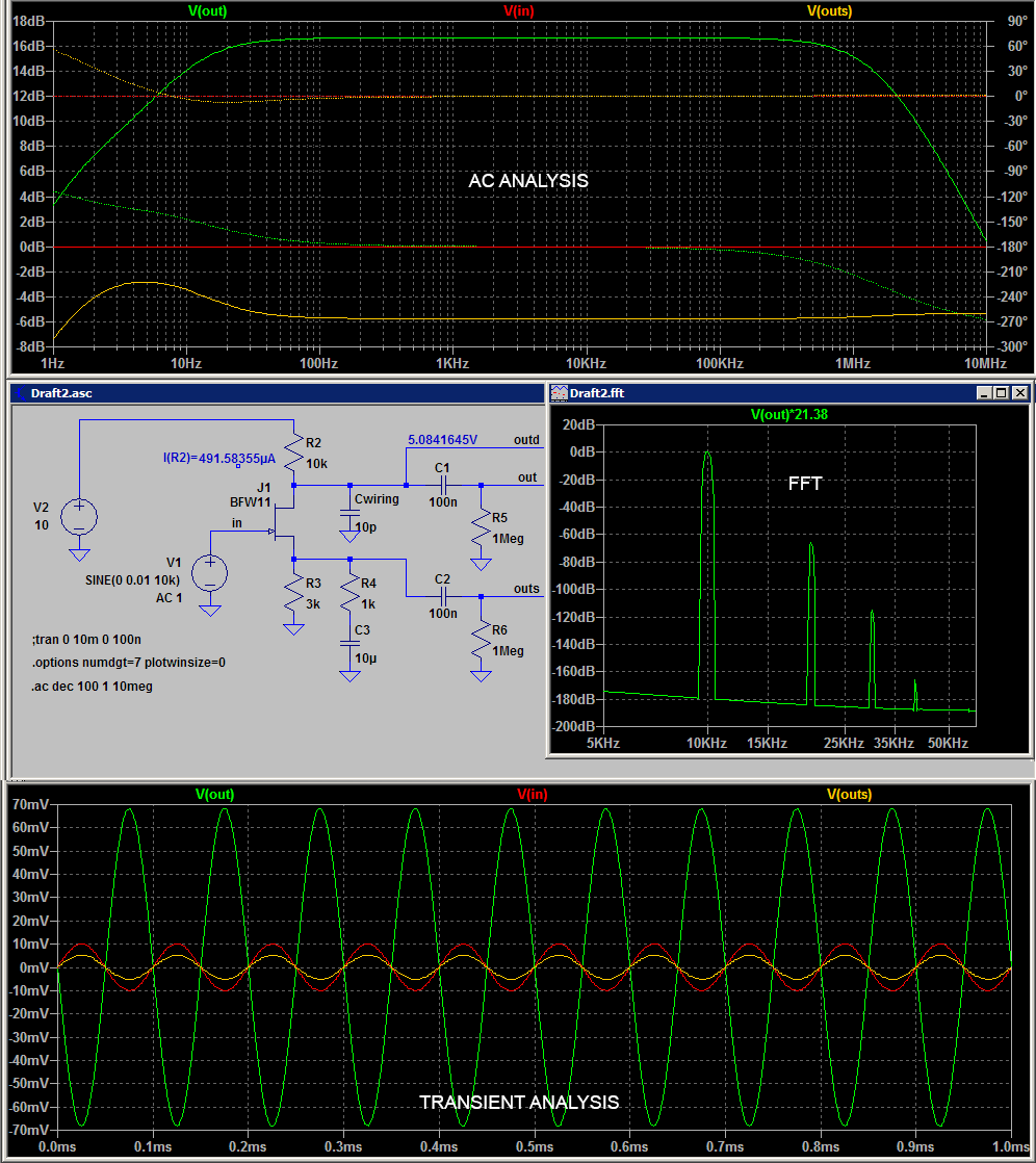
In response to Lexor's comment below, you can probably make this work with a BFW11 JFET. I added a Spice model in LTspice's standard.jft library to simulate this in LTspice. I have no idea about the model's accuracy, thus, view the simulation with suspicion.
.MODEL BFW11 NJF(VTO=-2.0850 BETA=1.24635m BETATCE=-0.5 LAMBDA=2.46045E-2 RD=1.68159E1 RS=1.68159E1 CGS=2.25000p CGD=2.25000p PB=9.32203E-1 IS=2.16894E-16 XTI=3 AF=1 FC=0.5 N=1 NR=2 MFG=PHILIPS)
The simulation shows a drain current of 492 uA with a 3k source resistor. The value of R3 was empirically determined which took about four tries.
If used as an amplifier (output taken at V(out)) the second harmonic is down 65 dB with a 10 mVp input as shown in the FFT. At 100 mVp input, the second harmonic is down slightly better than 40 dB. Note, the FFT was performed using a stop time of 100 ms in the transient analysis.
If you use this circuit in a source follower configuration, you can probably drive a 1 or 2 meter cable. If the output is taken from the drain, you will need a buffer due to the high impedance of the output node. You can use a source follower as a buffer with very little penalty in noise performance (I have found that JFETs used as a source follower are inherently low-noise).
-
\$\begingroup\$ Would my jfet BFW11 be able tk work though? \$\endgroup\$– LEXOR AICommented Sep 23, 2023 at 9:57
-
\$\begingroup\$ @LEXORAI I have edited my post showing that there is a possibility of the BFW11 being biased at Id = 500 uA with a self biasing technique. \$\endgroup\$– qrkCommented Sep 23, 2023 at 19:01
-
\$\begingroup\$ I can hear my voice on the computer only if I yell into the mic very loudly though \$\endgroup\$– LEXOR AICommented Sep 23, 2023 at 19:29
-
\$\begingroup\$ And you are using voltage of 10 volts a computer port has 2.8 volts \$\endgroup\$– LEXOR AICommented Sep 23, 2023 at 19:37
-
\$\begingroup\$ @LEXORAI If you change the power supply to 2.8 V, then R2 needs to change for correct biasing. Perhaps make R2 = 1.5k. To get better distortion, probably need to reduce operating current to around 400 mA, so change R3 = 3,9k. You'll need to reduce R4 (perhaps zero) to get any gain which will be at most around 6 dB since the internal source resistance will be fairly high due to the low drain current. \$\endgroup\$– qrkCommented Sep 23, 2023 at 20:12
Here is a typical JFET aimed at high-volume electret microphone applications - Unisonic TF2123.
It has a rather low (and relatively tightly specified- by binning) Idss compared to typical low-noise JFETs such as the wonderful BF862 (RIP) which were aimed at AM radio front ends. By almost two orders of magnitude.
They appear to be easily available from stock wherever electret microphones are made.

