2
\$\begingroup\$

I'm not an electronic expert at all, but I'm keen on various electronics and stuff, and I like to watch videos where the different laptops are fixed. And in nearly every repair there is a multimeter used to test different components of the motherboard to see if their resistances/voltages are normal.

I see that he puts one of the multimeter probes to one of the through-holes of the board (which are used to connect different layers of PCB, AFAIK), and the other probe is connected to the component/output he want to test (photo).

But it is unclear for me why do you need to put one of the probes to that hole. How does it work? How is the circuit completed during the measurement?

I've searched for info in the net, but I've only managed to figure out that these holes are called "the ground terminals" and they connect the motherboard to the case of a laptop (guy from these videos calls these holes just "ground"). How does it work?

And also, does it matter to which hole to put one of the multimeter probes (there are several of them on the motherboard)?

*The photo is taken from the youtube video, author: https://www.youtube.com/@notebook31 ; video: https://www.youtube.com/watch?v=KuaqOT-NyKQ&t=752s (at 12:29)

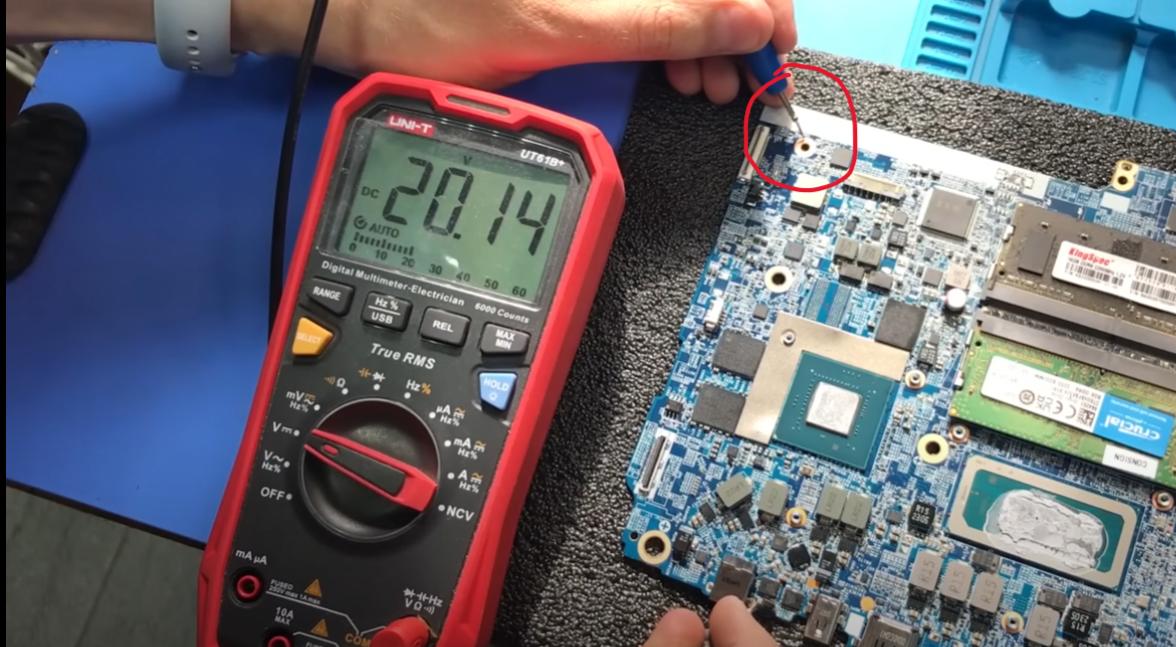
A technician uses the multimeter to test different components of the motherboard

\$\endgroup\$
0

1 Answer 1

4
\$\begingroup\$

Most voltages in a circuit diagram are referred to a "so-called" ground or 0V. The technician is placing the black (negative ) probe at a convenient "ground reference" point. There are others if you know "how" to look for them.

The red probe (positive) is then placed at a point where a voltage is to be measured The result is compared to an accepted value either from a schematic diagram or experience.

\$\endgroup\$
5
  • \$\begingroup\$ You see, I'm not an expert in electronics, so it is hard for me to understand this. The entire Earth can also be a reference point for measurement? If he had a hypothetically-long negative probe, which would go outside from the building and plugged to the ground, multimeter would also show the voltage? \$\endgroup\$
    – Gog
    Commented Sep 25, 2023 at 17:35
  • 1
    \$\begingroup\$ @Gog: "Ground" is a much-misused term in electronics. In most cases, "Ground" is just the part of the circuit we consider "Zero volts", and use as a reference when measuring voltages elsewhere. We talk about "Ground" in little test circuits, things you build on a plastic breadboard, sample circuits in text books, and many other places without implying any connection to The Earth. \$\endgroup\$ Commented Sep 25, 2023 at 18:15
  • \$\begingroup\$ 1) So that hole he put the negative terminal to is connected to the circuit? (because I've also seen that the resistance of a particular line is also measured this way, and the circuit must be completed when measuring the resistance) \$\endgroup\$
    – Gog
    Commented Sep 25, 2023 at 18:52
  • 1
    \$\begingroup\$ @Gog: The technician is picking a point he or she knows is connected to ground or possibly some other point of interest. This could be a screw, a via hole or a pad. Depends on what they are doing. \$\endgroup\$ Commented Sep 25, 2023 at 21:57
  • \$\begingroup\$ @user1850479 So, to measure voltage of some point on the motherboard, you can put the negative terminal not only to that via-hole, but also to other conductive things connected to ground? They must be on that board or they can lay somewhere else? Can you put the negative terminal on a penny lying on a table to measure the voltage? (maybe it's a bit out of the topic, but it's just interesting for me to know) \$\endgroup\$
    – Gog
    Commented Sep 26, 2023 at 13:13

Your Answer

By clicking “Post Your Answer”, you agree to our terms of service and acknowledge you have read our privacy policy.

Not the answer you're looking for? Browse other questions tagged or ask your own question.