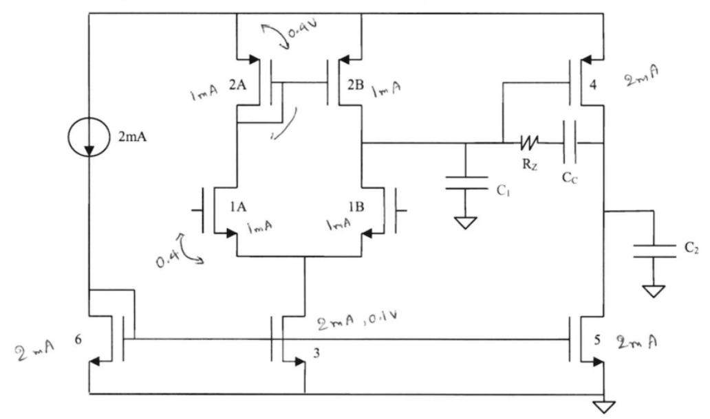
I'm working through a solved example problem on compensation of a two-stage op amp. For extra context, this example problem is originally from an exam of a now-concluded course offering, so it is meant to be solve-able without simulation, numerical methods, etc. The link has all the relevant figures/details including bode plots but I've included a picture of the topology and given component values below.
The example problem (labeled problem 2.i in the attached images) presents a set of values for the amplifier including the Miller compensation capacitor \$C_C\$. The question asks for the minimum value of \$C_C\$ that gives a 45 degree phase margin in unity gain feedback. The given answer is 0.03 pF, or anything in the range of 0.01 pF to 0.1 pF. This is a smaller range than what I can come up with, reasoning below.
First approach:
One expression for the non-dominant pole location of this amplifier topology comes from the dominant-pole approximation. Note that although as seen in the attached plots the uncompensated pole locations are at the same frequency (1 Grad/s), for the given value of \$C_C\$ they are actually reasonably far apart, so this approximation seems justified. For a transfer function
$$H(s)=\frac{A(s)}{1+b_1 s + b_2 s^2}$$
where \$p_1, p_2\$ are not very close together, we have that
$$p_1 \approx\frac{-1}{b_1}=\frac{-1}{R_{o1}(C_C+C_1)+R_{o2}(C_C+C_2)+G_{m2}R_{o2}R_{o1}C_C}\approx\frac{-1}{G_{m2}R_{o2}R_{o1}C_C}$$
where the last approximation holds if the Miller effect dominates and the compensation capacitor is relatively large. We have for the nondominant pole
$$p_2\approx\frac{-b_1}{b_2}=\frac{1}{p_1 b_2}\approx\frac{-G_{m2}R_{o2}R_{o1}C_C}{R_{o1}R_{o2}(C_1C_2+C_C C_1 +C_C C_2)}=\frac{-G_{m2}C_C}{C_1 C_2 +C_C(C_1+C_2)}$$
For a 45 degree phase margin, the nondominant pole sits on top of the unity-gain crossover frequency, assuming that the dominant pole has contributed all 90 degrees of its phase shift. So the condition is
$$\omega_u=|p_2|=\frac{G_{m2}C_C}{C_1 C_2 +C_C(C_1+C_2)}$$
As \$C_C\$ decreases, \$p_1\$ increases, \$\omega_u\$ increases, and \$p_2\$ decreases. An approximate result for \$\omega_u\$ is \$\omega_u=|A_0||p_1|=\frac{G_{m1}}{C_C}\$. For the given values, this is \$10^{10}\$ rad/s, which matches with the plots. Plugging in and solving, we get \$C_C=0.24 pF\$, which is far outside the answer's given range (0.01 to 0.1 pF).
Second approach:
Assume a simpler relationship for \$p_2\$, so instead assume that \$p_2\$ is proportional to \$C_C\$, so we have \$p_2=p_{2,0}\frac{C_C}{C_{C,0}}\$, where the extra 0 subscript indicates the nominal values (\$p_{2,0}=10^{11}\$ rad/s, \$C_{C,0} = 1\$ pF). \$\omega_u\$ was already assumed inversely proportional to \$C_C\$. This leads to
$$C_C=\sqrt{\frac{\omega_{u,0}}{p_{2,0}}C_{C,0}^2}\approx 0.32 \text{ pF}$$
which is even further out of the previous range.
Third approach:
Assume that exactly one of \$\omega_u\$ or \$p_2\$ are constant with respect to \$C_C\$ and the other one is inversely or directly proportional to \$C_C\$, respectively, as in the second approach. This approach leads to
$$C_C=\frac{\omega_{u,0}}{p_{2,0}}C_{C,0}=\text{0.1 pF}$$
This is the top of the provided reference range of 0.01 to 0.1 pF. The reference solution uses a non-inclusive less-than so it seems that 0.1 pF may or may not have been considered close enough, but at least this is progress. However, I'm not sure how to derive anything closer to 0.01 pF or the "main" given answer of 0.03 pF.
Fourth approach:
This approach doesn't actually work at all but I'm including for completeness, as it's the only other thing I can think of besides running a simulation. We could assume that the unity-gain frequency is fixed at its nominal value and instead assume the more accurate expression for the nondominant pole, i.e.
$$p_2=\frac{-G_{m2}C_C}{C_1 C_2 +C_C(C_1+C_2)}$$
However this approach fails as solving yields \$C_C=-0.5 \text{ pF}\$ (this isn't because of the minus sign in the above expression; when plugging in and solving I'm actually using the magnitude of \$p_2\$ since \$p_2\$ is a pole of the s-domain transfer function).
Are there any other approaches I'm missing for trying to derive the given result?


