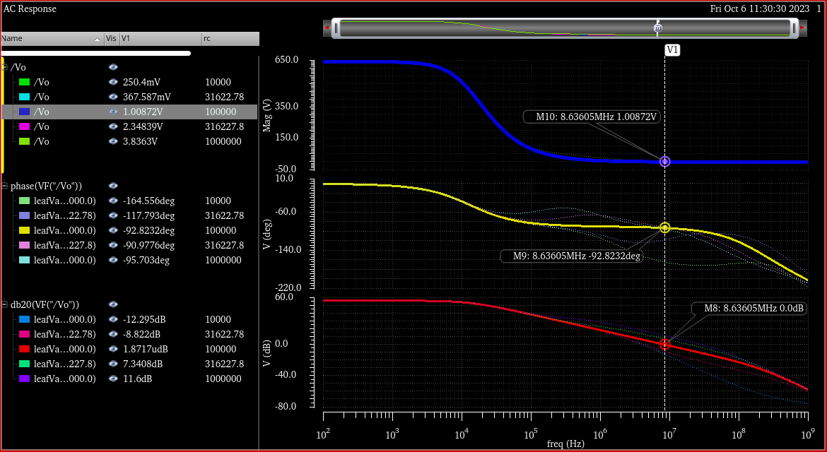
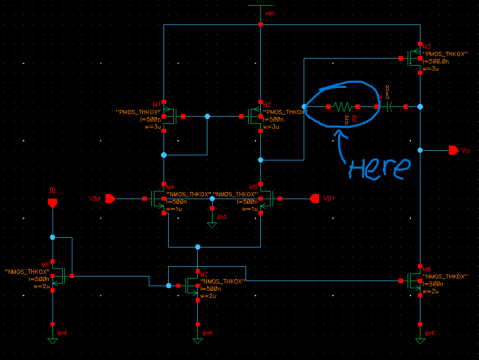
I wonder why there is a compensation resistor in some CMOS Op-Amp circuit shown here. What is the purpose of this? I tried to vary it and this is what I got for unity gain of each value. Based on many website formula, the unity gain frequency can be calculated as W = gm4/C_c, but it is clearly not the case here. What is happening?
2 Answers
This compensation is called "Miller compensation". Purpose of the resistor is to eliminate the RHP zero that occurs without the resistor. The RHP zero is a very bad thing for stability hence needs to be eliminated. There are techniques for eliminating the RHP zero and addition of the resistor is one option. The resistor value is usually set such that the RHP zero moves to the real axis.
Take a look at for example this article to understand the RHP zero and why it is bad for stability
https://pallen.ece.gatech.edu/Academic/ECE_6412/Spring_2004/L130-OpAmpCompII(2UP).pdf
-
1\$\begingroup\$ @tobalt, I've added a link which talks more about this compensation and the RHP zero. As mentioned in the article, an RHP zero causes increase in magnitude and lags the phase which is why it has high chances of making the system unstable \$\endgroup\$– saiCommented Oct 22, 2023 at 7:03
-
\$\begingroup\$ Several opamps are available both in a "unity gain stable" version and a version that is stable only for larger gains (like g>5) because larger gains feed back smaller signals. The decompensated opamps tend to have less noise and much higher GBW products and faster rise times, but designing a circuit around them with sufficient phase margin for stability at the 0dB gain point may require extra care. \$\endgroup\$ Commented Oct 22, 2023 at 12:16
I'm sure other answers can give a fuller picture, but here is a short intuitive assessment.
The output stage is a common-source stage with high voltage gain. The capacitor shorts this stage at high frequencies, brining its voltage gain gradually down to 1 as you move to higher frequencies. Lower gain helps with stability typically.
The resistor prevents that the gain drops all the way to 1, and it will guarantee some residual voltage gain at high frequencies. So it can extend the unity gain bandwidth at the expense of stability
This contradicts sai's (probably correct) assessment, so take it with a grain of salt.


Compensation Resistor in some CMOS Op-Amp circuitis a so-called nulling resistor and yoursome CMOS Op-Amp circuitis quite similar to (if not identical with) the circuit in Design method for two-Stage CMOS op amp..., section 4.2. Two-stage Op Amp with Miller Capacitor and Nulling Resistor, page 8/11 (mpra.ub.uni-muenchen.de/102931/1/MPRA_paper_102931.pdf). Searching web for keywords 'nulling resistor, CMOS opamp, Spectre' you will find a number of similar schematics with more or less detailed analysis of[w]hat is happeningwith stability and GBW for these designs \$\endgroup\$