The next story is based on guesses. A less random answer is inserted to the end after the questioner gave more details.
Assume the wavequide is in parallel with the z-axis. All planes which are parallel with the xy-plane can be called t-planes. They are "transversal", as already guessed in the older answer. They are equivalent because the field distributions are the same in every t-plane, there's only phase differences caused by different z-values. The waveform is assumed to be the simplest possible.
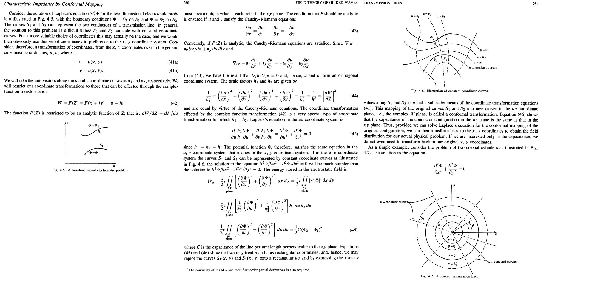
The electric field in a t-plane must meet the metal perpendicularly. The equipotential curves of the field must be perpendicular with the field trajectories.
The math theory of potential (actually the theory of harmonic functions) shows there's a tight interconnection between the next 2 patterns:
Curved, but locally rectangular grating made of field trajectories and equipotential curves
A rectangular grating in the xy-plane made of straight lines which are parallel with the x and y axles.
Tight interconnection means they are equivalent. Solve a potential boundary value problem in one means it's solved also in the other.
The curved, but locally rectangular grating in the t-plane can be made with a conformal mapping which transforms the rectangular xy-plane lines to field trajectories and equipotential curves.
Finding such conformal mapping is essentially done when one solves the Laplace differential equation of the potential. It's often possible only with numerical iterations. But the theory of analytic functions (=differentiable functions of a complex variable) has given an explicit formula for the wanted mapping. It's known as Schwartz-Christoffel transformation which can be used when the metal boundaries in the t-plane are made of straight line segments. Unfortunately the transform still must be often calculated numerically.
I do not have the research report which puzzles you with the t-plane and conformal mapping. But Schwartz-Christoffel transformation is mentioned and used there. I saw it accidentally when a research report marketing website showed just the right page as a short preview snippet. It was kept partially visible few seconds before the snippet was replaced by text "Want to read it? Then click Buy it!".
Understanding the details of the potential theory and the theory of analytic functions needs easily university level full math studies worth 1...2 years. Prepare to see something like this:
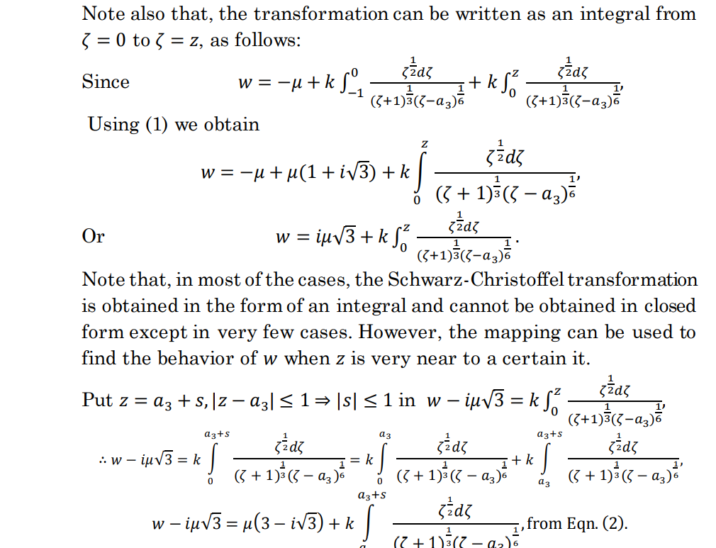
The screenshot is taken from here: https://www.euacademic.org/UploadArticle/4726.pdf
It's report "Conformal Mapping as a Tool in Solving Some Mathematical and
Physical Problems" by Wiam Ali Ayad, Omar Ismael Elhasadi, Zaynab Ahmed Khalleefah and Abdussalam Ali Ahmed.
If you happen to like the hieroglyphs above, see also this https://www.hindawi.com/journals/mpe/2010/742039/ It's one of the source texts mentioned in the report above. Fortunately there's available some practical tools for the rest of us. See this demonstration of one commercial product: https://demonstrations.wolfram.com/ElectrostaticFieldsUsingConformalMapping/
But its's not the only way. Michael Faraday, a serious physicist who made the concept of the field popular, was not at all a mathematician. Obviously he was able to see things intuitively like some famous inventors (Edison, Tesla). He was promoted from a laboratory assistant to a respected scientist because time after time he happened to hit the point and proved it with practical experiments. His favourite method for solving field structures was to draw on a paper the intuitively right rectangular grating. I have seen the same method used in engineering textbooks. They were written before numerical computing methods became generally available.
ADDITION after seeing the augmented question with the inserted 3 pages of the problematic text:
Seemingly I have written only some qualitative elementaries of the general theory - a long blahblah which doesn't answer the actual problem which appeared when reading the first pages of the problematic text. That happens when answers are written based on guesses.
Name t-plane in the problematic text Fig.2b does not mean transversal, it simply comes from the used plane point symbols. t-plane is also transversal, but the t doesn't come from that.
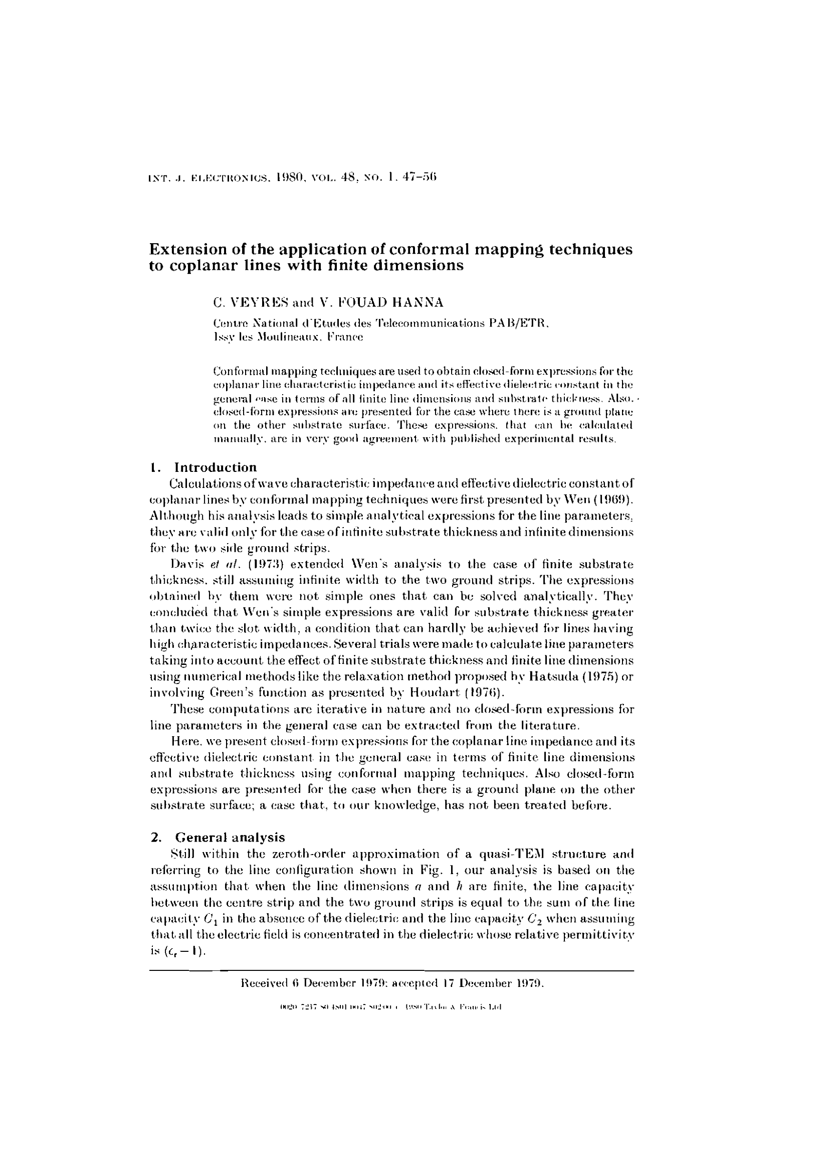
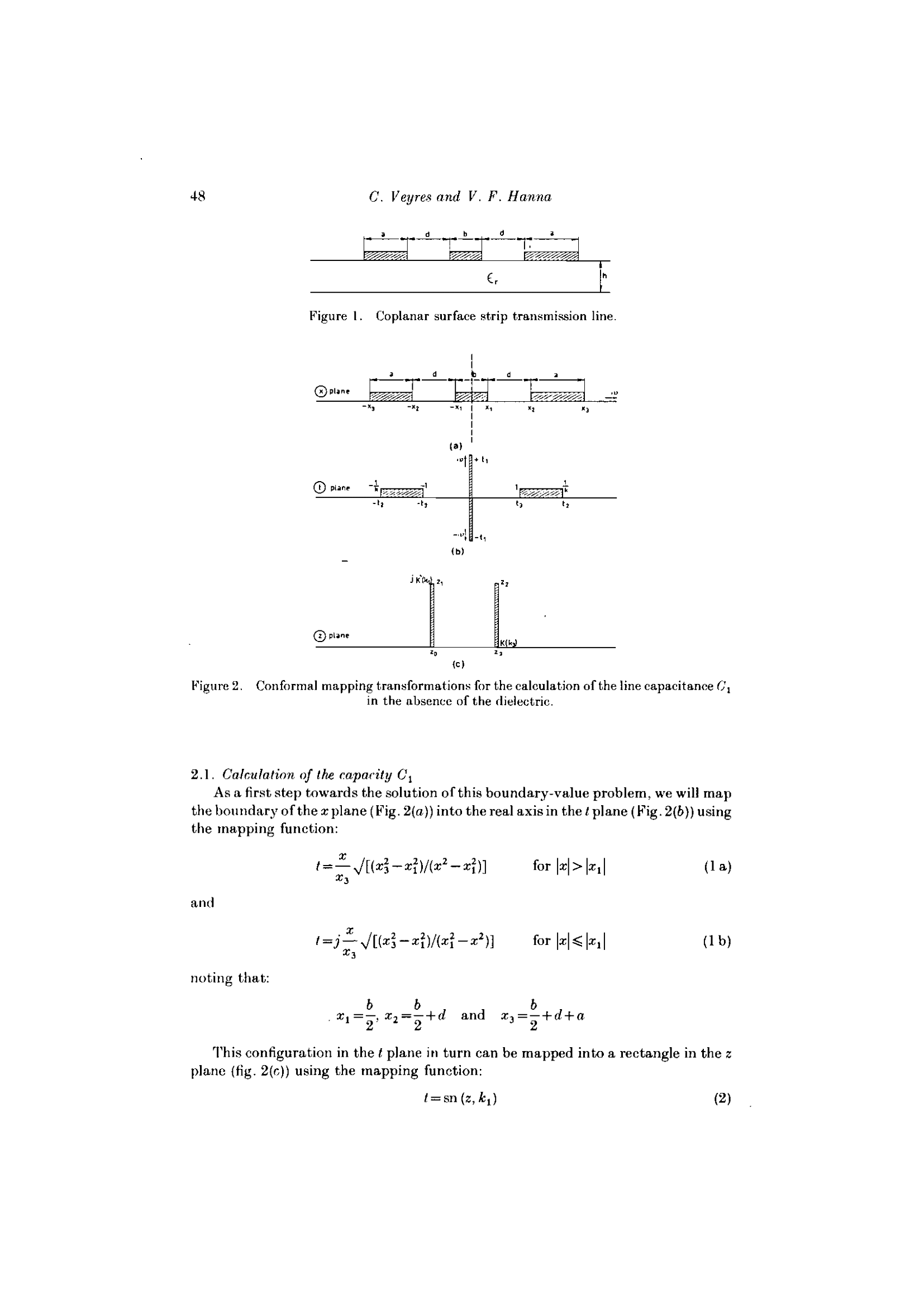
In Fig.2a The author shows at first the finite width waveguide profile with its original dimensions in a complex plane called x-plane. By the way: It's transversal for the simplest possible waveform. He has used symbols plusminus x1, x2 and x3 for the points in the real axis. The author has seen it's handy to call his original complex plane x-plane. Symbol x is used later as a complex variable which can be any point in his x-plane.
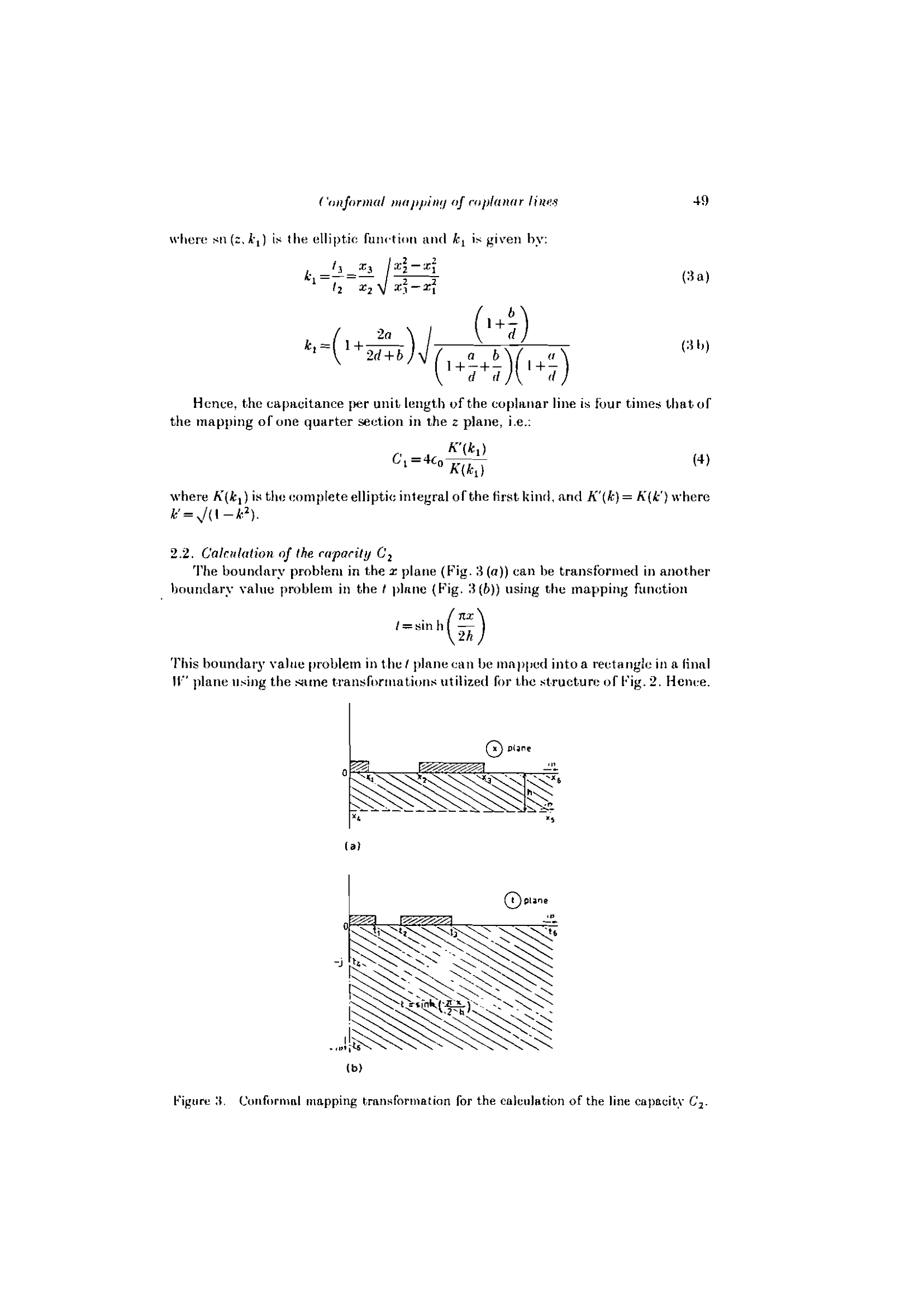
According the usage of the conformal mappings in the potential theory the author maps the x-plane (with the shown conformal mapping) to a new complex plane and that plane is his t-plane. The name probably is selected randomly. t happened to be a good looking free letter. Now he has got an equivalent potential boundary value problem which he solves later. The mapping function (=expressions which change x-plane point complex variable x to t-plane point complex variable t) are presented without a slightest hint in pages 1...3 how the author succeeded to invent the good expressions which lead to useful results. Hopefully there's later some explanations.
The t-plane geometry and the equivalent potential problem there is only an intermediate step. It's converted to a new equivalent potential boundary value problem with a new mapping. The plane of the new geometry is called z-plane (maybe again a good looking free letter). The author says that final calculation is possible with closed form formulas in z-plane. Again: no hint in pages 1...3 how the author succeeded to invent the 2nd useful mapping.

