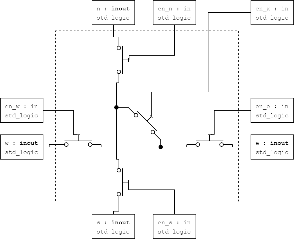
I want to model a crosspoint switch with 4 inout ports that can route a signal coming from any of the inout ports to any other combination of the remaining inout ports depending on a series of enable SPST switches. This is for simulation only and not for any form of hardware implementation.
It should behave like the following picture:

My approach was the following VHDL code:
library ieee;
use ieee.std_logic_1164.all;

entity spst_xpoint is
  port(
    d_n  : inout std_logic;
    d_s  : inout std_logic;
    d_e  : inout std_logic;
    d_w  : inout std_logic;
    en_x : in    std_logic;
    en_n : in    std_logic;
    en_s : in    std_logic;
    en_e : in    std_logic;
    en_w : in    std_logic
  );
end entity;

architecture arch of spst_xpoint is
begin

    d_n <= d_s when (en_n = '1' and (d_s='0' or d_s='1') and en_s = '1') else
           d_e when (en_n = '1' and (d_e='0' or d_e='1') and en_e = '1' and en_x = '1') else
           d_w when (en_n = '1' and (d_w='0' or d_w='1') and en_w = '1' and en_x = '1') else 'Z';
    d_s <= d_n when (en_s = '1' and (d_n='0' or d_n='1') and en_n = '1') else
           d_e when (en_s = '1' and (d_e='0' or d_e='1') and en_e = '1' and en_x = '1') else
           d_w when (en_s = '1' and (d_w='0' or d_w='1') and en_w = '1' and en_x = '1') else 'Z';
    d_e <= d_w when (en_e = '1' and (d_w='0' or d_w='1') and en_w = '1') else
           d_n when (en_e = '1' and (d_n='0' or d_n='1') and en_n = '1' and en_x = '1') else
           d_s when (en_e = '1' and (d_s='0' or d_s='1') and en_s = '1' and en_x = '1') else 'Z';
    d_w <= d_e when (en_w = '1' and (d_e='0' or d_e='1') and en_e = '1') else
           d_n when (en_w = '1' and (d_n='0' or d_n='1') and en_n = '1' and en_x = '1') else
           d_s when (en_w = '1' and (d_s='0' or d_s='1') and en_s = '1' and en_x = '1') else 'Z';

end architecture;
If I simulate this in the case where I drive the d_n port with a signal, and enable en_n, en_e and en_x to pass the signal to the d_e port, it works.
As soon as I want to drive multiple output ports (e.g. enabling en_s together with en_e and en_x) the simulation aborts because it is caught in a delta cycle loop (ghdl:info: simulation stopped @90ns by --stop-delta=5000).
Is the simulation of such an entity in VHDL even possible having such generic inout ports where the driving source is unknown?
Are there other approaches this could be made to work? Instead of the concurrent assignment of all 4 ports, a process with a sensitivity on all 4 ports could maybe work.
Testbench for reference:
library ieee;
use ieee.std_logic_1164.all;
use ieee.numeric_std.all;

entity tb_switchpoint is

end tb_switchpoint;

architecture bh of tb_switchpoint is

  component spst_xpoint is
    port(
      d_n  : inout std_logic;
      d_s  : inout std_logic;
      d_e  : inout std_logic;
      d_w  : inout std_logic;
      en_x : in    std_logic;
      en_n : in    std_logic;
      en_s : in    std_logic;
      en_e : in    std_logic;
      en_w : in    std_logic
    );
  end component;

  constant CLK_PERIOD: TIME := 5 ns;

  signal clk        : std_logic;
  signal i_n  : std_logic := 'Z';
  signal i_s  : std_logic := 'Z';
  signal i_e  : std_logic := 'Z';
  signal i_w  : std_logic := 'Z';
  signal en_x : std_logic := '0';
  signal en_n : std_logic := '0';
  signal en_s : std_logic := '0';
  signal en_e : std_logic := '0';
  signal en_w : std_logic := '0';

  signal clk_count  : std_logic_vector(31 downto 0) := (others => '0');
begin

  -- generate clk signal
  p_clk_gen : process
  begin
   clk <= '1';
   wait for (CLK_PERIOD / 2);
   clk <= '0';
   wait for (CLK_PERIOD / 2);
   clk_count <= std_logic_vector(unsigned(clk_count) + 1);
  end process;

  p_test : process(clk)
  begin
    if unsigned(clk_count) = 7 then
      en_n <= '1';
    end if;
    if unsigned(clk_count) = 9 then
      --en_s <= '1';
    end if;
    if unsigned(clk_count) = 11 then
      en_x <= '1';
    end if;
    if unsigned(clk_count) = 13 then
      en_e <= '1';
    end if;
    if unsigned(clk_count) = 15 then
      en_w <= '1';
    end if;
  end process;

  i_n <= clk_count(0);
  xpoint_dut_raw : spst_xpoint
    port map (
      d_n  => i_n,
      d_s  => i_s,
      d_e  => i_e,
      d_w  => i_w,
      en_x => en_x,
      en_n => en_n,
      en_s => en_s,
      en_e => en_e,
      en_w => en_w
    );
end bh;
