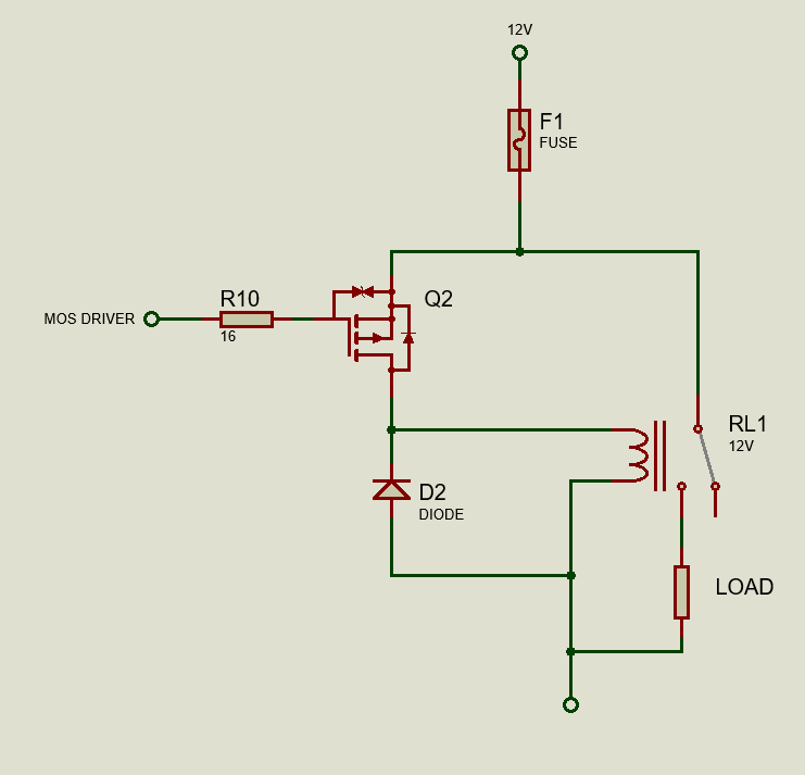
I am currently making an automotive circuit that controls some automotive accessories (personal project not for production). In my circuit, I will be controlling some automotive relays and in any relay implementation I have seen so far there has always been some sort of flyback protection. I understand that you should always place a flyback protection but I am having doubts on what kind should be used. In the past my default setup would be a diode.
Recently, though, I have read that using a diode is actually detrimental to the relay as it will reduce the lifespan of the relay. When I try to research more about this topic, articles from google seems to be on the contrary, it could be very well be that these articles meant that a diode is better than nothing.
Another point of evidence that contradicts the claims is that automotive relays come in variants that have either a built in diode, or a built in resistor. Articles on google about flyback protection mostly mentions a diode as the go to component, very few of them mentions using a resistor or a resistor/diode combo.
Is it true that using a diode alone is not ideal as a flyback protection against inductive loads? Is it maybe a relay specific thing? I could not understand why a diode is bad for the relay.
I read several white papers and my two cents on the matter is: It would seem that if it were in an ideal world, the best flyback protection is basically a short circuit as the back EMF can be spent on the wires very very quickly, but that would make no sense as there would be no current passing through coil, which makes it meaningless. Having said that, the next best thing is using a resistor as a flyback protection, when the magnetic field of the coil from the relay collapses, the coil basically becomes a current source (voltage source also depending how you look at it) and the energy can be safely dissipated into the wire traces and the resistor (not back through the main power supply and the gate drivers of the coil potentially destroying them).
This has a major drawback, though, as the resistor will always have some power going through it while the relay is on. The diode would have not have this "leakage" problem but my theory where the problem is with a diode: As the back EMF voltage goes below the diode forward voltage, it would be the equivalent of having no flyback while still having a little bit of power left that needs to be dissipated, how this translates to the physical world is the relay would actually take longer to fully release, thus arcing for a longer period of time on the contacts occur, thus destroying them prematurely. This is just my theory though, feel free to correct it.
Then there is a TVS diode, specifically made to shunt excess current very quickly, but is it better than a resistor though? Don't TVS diodes just have a lower forward voltage?
Is the resistor the best flyback protection for a relay, and maybe other inductive loads? If so, how do I know what resistance I should choose?
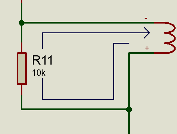
Assuming this relay, this is a bit tricky to balance since lowering the resistance too much means I have to use bulky high power resistors, having it too high would also mean the back EMF voltage could be too high also and destroy my drivers. I could always use a relay that has a built in resistor but I think that would cheat me out of the learning opportunity I have now.
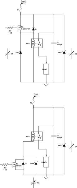
There are also hybrids like a TVS + resistor combo but I'm not really sure how much better they are.
EDIT:
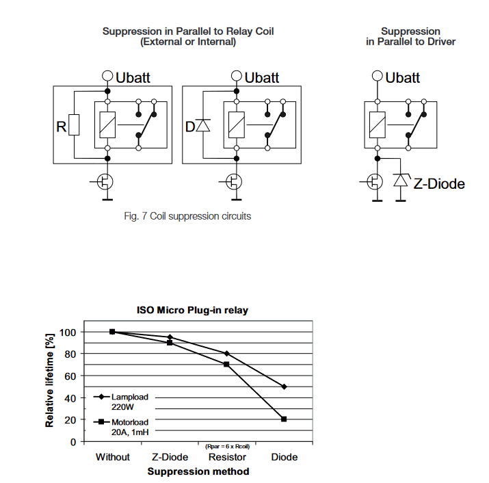
Here are two application notes that support the claim of diodes reducing the relay lifespan:
- White Paper: Coil Suppression Can Reduce Relay Life (Link does not work all the time)
- Automotive Relay Application - Page 3 claims that a diode parallel to the coil reduces the lifespan down to 20% for motor loads.


