2
\$\begingroup\$

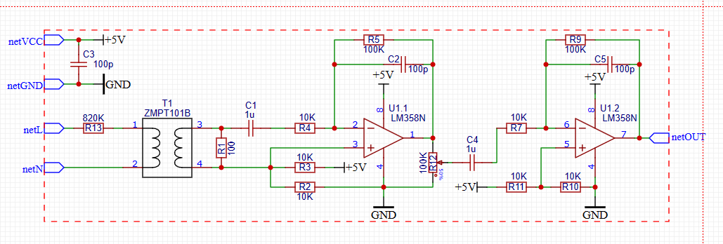
ZMPT101B Circuit

Why do we use this capacitor in the opamp and why do we superimpose it on the DC voltage and then destroy it again with the capacitor?

I got some answers here, but as @SamGibson pointed out, I opened this thread so that the question does not turn into a "chameleon question".

First of all, let me state everything exactly. This circuit is a commercially available AC Main line voltage meter module, commonly known as an Arduino module.

This circuit is manufactured to be (Input: 50 Hz / 80-220V, Output: 0-3.5V).

  1. What is the purpose of capacitors C2 and C5 considering the measurement purpose, measurement voltage and frequency? What could they be used for in this circuit? Could it be something like an integrator? It doesn't make sense to have a low pass filter because no signal other than 50Hz will enter anyway.
  2. Why is capacitor C1 there? I thought there was no offset on the AC voltage line?
  3. Why is the lower leg of R1 connected to the middle of R2 and R3? What is the purpose here?
  4. Is this a voltage transformer or a current transformer? What is the difference and how can you tell by looking at this circuit? We also talked to @Andyaka in the previous question. He stated that this small transformer is not suitable. And he is right because there is not even a proper datasheet. I wonder what you think about this issue, is it too much of a problem. Is there another 1:1 current transformer that can be used instead?
  5. When determining the R1 value, which data in the datasheet is used for the heating state of the transformer and with which formulas is it calculated?

I look forward to your answers.

\$\endgroup\$
5
  • \$\begingroup\$ Why are you repeating the same question asked in your previous post (about C2 and C5)? \$\endgroup\$
    – Andy aka
    Commented Nov 6, 2023 at 16:46
  • \$\begingroup\$ BTW I didn't say it wasn't suitable; I questioned its integrity as a part re quality assurance and data sheet anomalies. I said I wasn't convinced by what it was (based on the data sheet anomalies and lack of clear manufacturing and quality provenance). \$\endgroup\$
    – Andy aka
    Commented Nov 6, 2023 at 16:55
  • \$\begingroup\$ ZMPT101B : Small transformer datasheet 5nrorwxhmqqijik.leadongcdn.com/… \$\endgroup\$
    – Antonio51
    Commented Nov 6, 2023 at 17:39
  • \$\begingroup\$ @Andyaka - I asked again about C2 and C5 because I didn't get an adequate answer. I'm replacing the word adequate with adequate. When you look at the datasheet, it doesn't really provide very detailed data. \$\endgroup\$
    – bevren15
    Commented Nov 6, 2023 at 19:58
  • \$\begingroup\$ @Antonio51 - Thank you for adding the datasheet link. \$\endgroup\$
    – bevren15
    Commented Nov 6, 2023 at 19:58

1 Answer 1

1
\$\begingroup\$
  1. C2 and C5 stabilize the op-amps. They are good practice. Especially if someone were to substitute a faster op-amp.

  2. C1 is there to isolate the transformer secondary from op-amp’s DC offset, and from DC faults. Should the op-amp fail with DC on the inputs, without C1 the transformer core would saturate, and the transformer primary would potentially catch fire - if it weren’t for R13. It’s good practice either way, although it could be Muntz’d out.

  3. R1 is the load on transformer secondary. The AC voltage being measured is sourced from this resistor.

  4. With a relatively hard resistive load on the secondary, and a relatively high primary resistance, it’s likely a current configuration, although it’s mostly a matter of perception. The transformer doesn’t really have distinct operating modes. They are only an aid to understanding and a way to express design intent.

  5. Assume the primary is a short. R13 develops a mains-voltage-proportional current on the primary. The secondary transforms the current by the inverse of turns ratio and it gets converted to voltage on R1. R1 ideally would be zero ohms in this case, and a small current shunt would be used for measurement. That’d give highest possible linearity. Transformer linearity goes down as the voltage goes up in this case. R1 is a bit higher than zero to make the circuit cheaper to put together. It acts as a current shunt.

\$\endgroup\$
2
  • \$\begingroup\$ Sorry but only the reason for C1 was an answer I was looking for. Thank you very much even for that. Every piece of information is worth gold. It is not clear in my mind about the others. For example, how will C2 and C5 stabilize the situation? How will it accelerate? Why is one leg of R1 connected between R2 and R3? \$\endgroup\$
    – bevren15
    Commented Nov 6, 2023 at 16:10
  • \$\begingroup\$ ...On the internet it is shown that CT and PT have different cores and internal structures, but I still don't understand the difference. Does 1:1 create an advantage or disadvantage? If R1 is chosen close to zero, the voltage drops too much and the error rate increases, if it rises, there will be other problems. Is there a formula for this, a mathematical datasheet data? \$\endgroup\$
    – bevren15
    Commented Nov 6, 2023 at 16:11

Your Answer

By clicking “Post Your Answer”, you agree to our terms of service and acknowledge you have read our privacy policy.

Not the answer you're looking for? Browse other questions tagged or ask your own question.