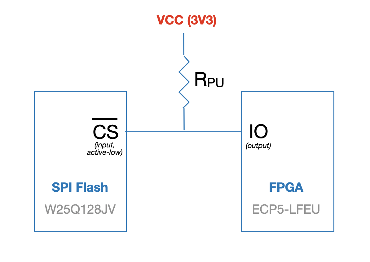
I have a circuit where I want to drive the CS# input on a SPI flash chip from an output pad on an FPGA. The flash IC's datasheet recommends putting an external pull up resistor to VCC on CS# to ensure that during power up the voltage at CS# will ramp at the same rate as the chip's VCC. Based on the flash IC's DC Electrical Characteristics table, I calculated that I could use as high as 1.5 MΩ pull-up in a configuration like this:
However, since 1.5 MΩ is a rather high upper limit on the pull-up resistor, I decided to look up the FPGA's maximum current sinking ability per I/O pad and per bank to see whether I could use a more normal-sized pull-up like 10k or 45k without damaging the FPGA.
That's where I ran into problems, and why I'm posing here to ask for help.
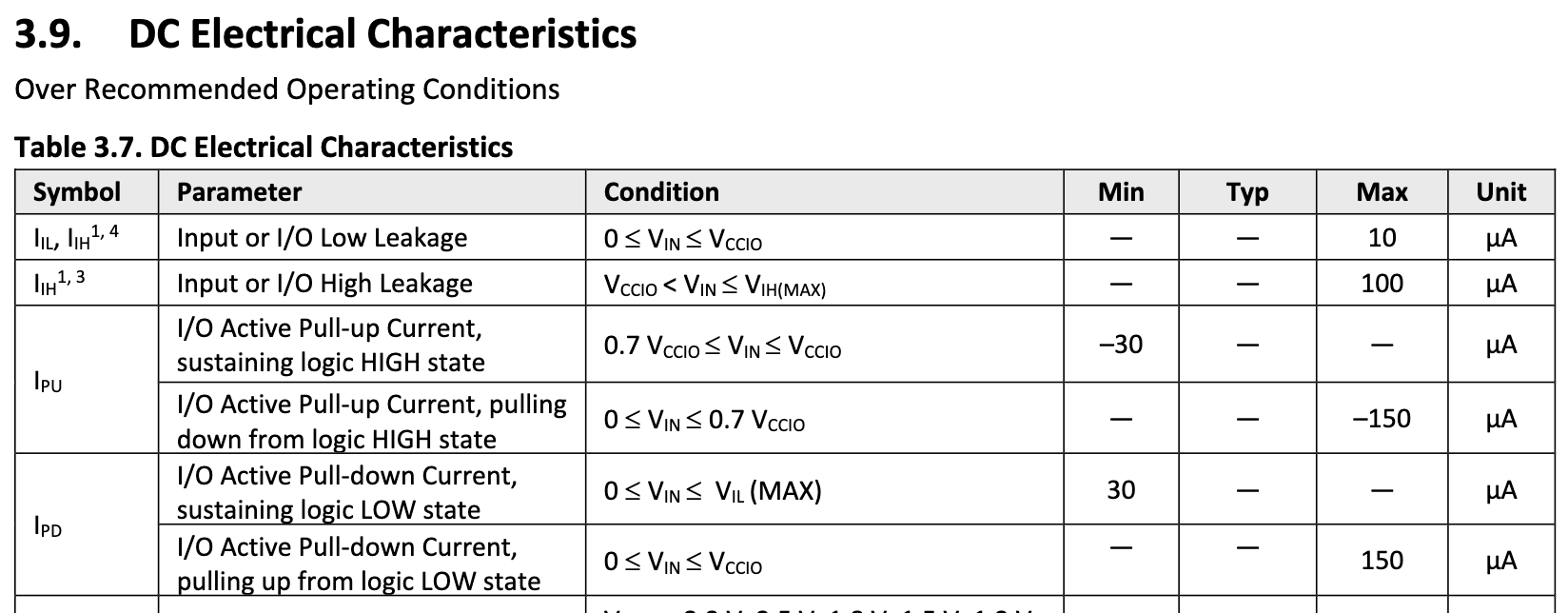
The FPGA is a Lattice ECP5U and it's main datasheet, table 3.7 in section 3.9 (page 50), appears to suggest that the maximum current an I/O pad can sink is 150 µA.
150 µA sounded surprisingly low to me, so I also consulted this FPGA's I/O pad configuration (sub-)datasheet. Tables 4.3 and 5.2 seem to state that single-ended LVCMOS33 I/O's can be programmed to source or sink up to 16mA.
The only sense I can make out of all this is that the FPGA's pad can sink up to 16mA if and only if it's configured as an OPENDRAIN=ON output (see sections 4.11.4, 5.2 and 5.3 of the I/O pad datasheet linked above, page 19).
But does this interpretation actually make sense? I'm not an FPGA expert, but normally open drain is used in multi-device, bidirectional buses like I2C. I've never seen open drain used to control a unidirectional, active-low chip select input. Is this typical for lower-end / budget FPGAs?
If anyone can see something that I'm misinterpreting or misunderstanding, I'd be grateful. Absent that, I would ask if there any downsides to using an open-drain output to drive an active-low chip select.


