2
\$\begingroup\$

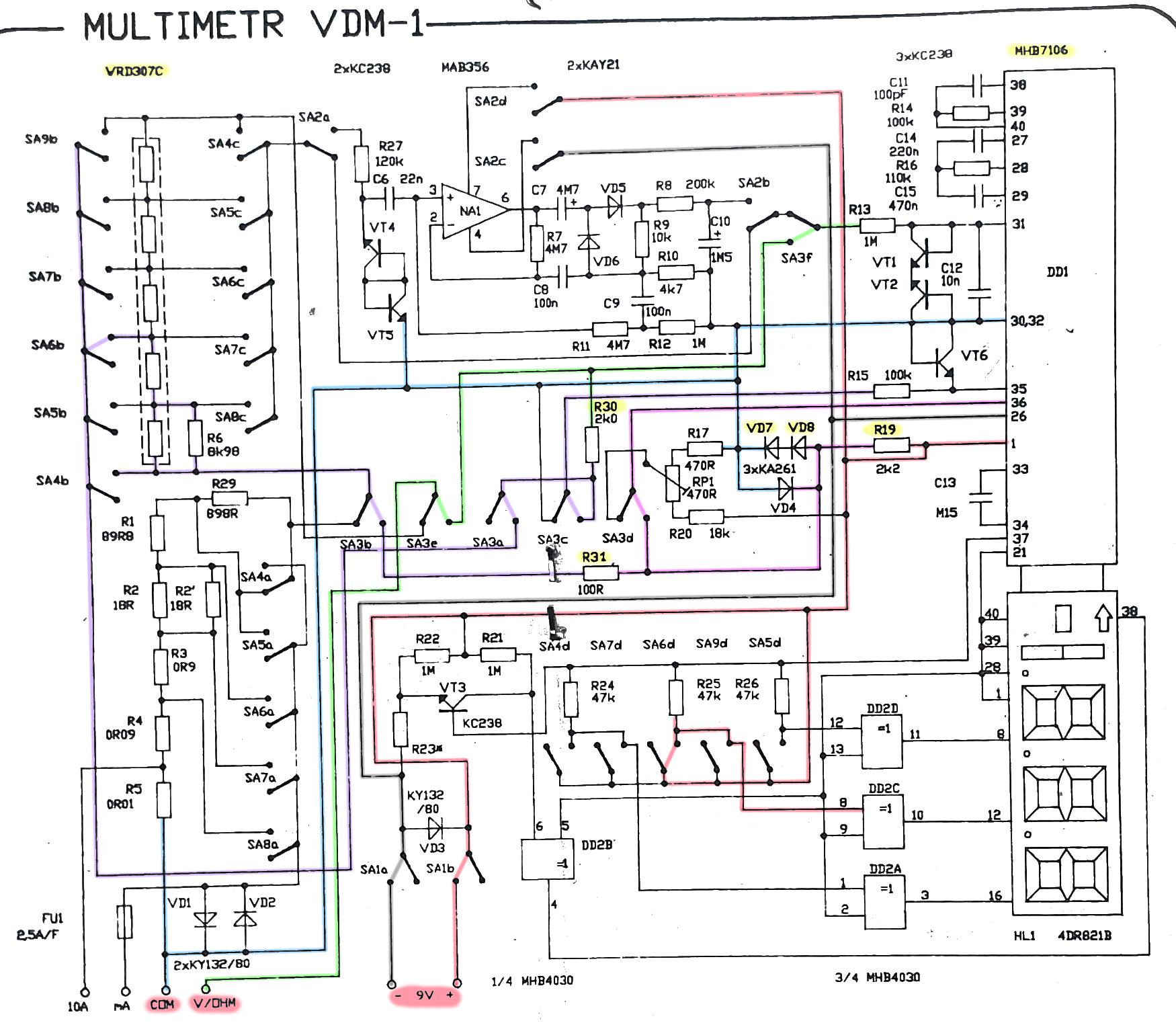
I have ancient multimeter, recently the resistance range shows very incorrect values (or nothing). I have schematics and started to analyze, but can not identify how the resistance measure works.

According to my knowledge resistance measurement works in a way that voltage drop across the measured resistor is converted to resistance, for this reason path from battery+ (+9V bottom of picture) to battery - (-9V bottom of picture) via COM/V/OHM must exists (for current to flow) and for me it is not possible to identify.

enter image description here

For next description following switches are in opposite position than pictured on schematics:

  • SA1: ON/OFF switch (in schematics OFF is painted)
  • SA3: ON for resistance measurement (in schematics OFF pictured for voltage/current measurement)
  • SA6: ON range selection, SA6 picked randomly as SA4 to SA9 are range switches, only one can be turned ON.

To complete explanation SA2 is AC/DC switch in position as on picture it should be in DC mode. For easier navigation in schematics the discussed paths are marked, hope correctly.

Battery +9V is connected to COM via sequence R19(2k2), VD9, VD7(diodes). Alternatively +9V can reach V/OHM via R19(2k2), R31(k1),VRD307C (selector resistances), R30 (2k)

But can not find path to -9V ?! Path for -9 is quite easy and it is connected only to negative power of the converter (MHB7106 - ancient piece of socialistic engineering) and display

To not bother with datasheet here are important pins of MHB7106 described:

  • 1: Power V+ in
  • 26: Power V- in
  • 36: Reference V+
  • 35: Reference V-
  • 31: Measured V+
  • 30: Measured V-
  • 32: COMMON (do not fully understand this pin, as it seems like sink path on first look, but then I would assume it must be connected to -9V, but it is NOT, if I would be connected to -9V it would ruin all voltage measures, because it IS connected directly to COM.

Any ideas how to troubleshoot/repair this multimeter? My knowledge in electronics is limited, also will be happy if someone can explain what I'm doing wrong.

PS: It is easier to buy new one, but this one is present from person that means a lot for me, for this reason I would like to repair this multimeter and continue using it.

Edit: Diode KA261 has forward drop of <1v, not very precise but can not find better datasheet. That would explain the 6.4V on COM, it gets there from 9V+ via R19-VD8-VD7, but COM is connected directly to pin 30 (V- measure). Another path is R19-R31-(range selector)-R30 to V/OHM and from V/OHM via R13 to pin 31 (V+ measure)

\$\endgroup\$
9
  • \$\begingroup\$ Have you tried changing the battery? \$\endgroup\$
    – Andy aka
    Commented Nov 7, 2023 at 20:57
  • \$\begingroup\$ Forgot to write in question, but battery is new and measured. \$\endgroup\$ Commented Nov 7, 2023 at 20:58
  • \$\begingroup\$ Do the voltage and current measurement ranges return plausible and correct values? Are the reference voltage sources at their nominal value? Just for curiosity: show the meter ;) \$\endgroup\$
    – datenheim
    Commented Nov 7, 2023 at 21:02
  • \$\begingroup\$ Voltages and current readings are OK (in the tolerances of socialistic engineering, we do not speak about any precise instrument). Photo you can see for example here cdn.aukro.cz/images/sk1687945372358/… (random photo found on internet, my looks identical) \$\endgroup\$ Commented Nov 7, 2023 at 21:09
  • 1
    \$\begingroup\$ start by cleaning the selector dial contacts \$\endgroup\$
    – jsotola
    Commented Nov 8, 2023 at 6:21

1 Answer 1

3
\$\begingroup\$

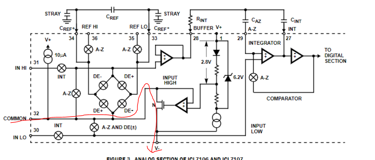
Let's start with the COMMON pin because it is key here. According to datasheet of ICL7106, of which your converter is almost an exact copy:

This pin is included primarily to set the common mode voltage for battery operation (ICL7106) or for any system where the input signals are floating with respect to the power supply. The COMMON pin sets a voltage that is approximately 2.8V more negative than the positive supply. This is selected to give a minimum end-of-life battery voltage of about 6V. However, analog COMMON has some of the attributes of a reference voltage. When the total supply voltage is large enough to cause the zener to regulate (>7V), the COMMON voltage will have a low voltage coefficient (0.001%/V), low output impedance (~15Ω), and a temperature coefficient typically less than 80ppm/×°C.

Lets look at the internal IC schematic as well: enter image description here

There is your connection to battery negative. It is essentially a simple voltage regulator for (Vin-2.8V).

Now let's do a simple analysis

Assume that the COMMON is regulating properly and Vin is 9V, then we will have COMMON=6.2V. I'm not entirely sure what the diodes VD7 and VD8 are exactly for but the two-in-series configuration is suspicious and I'm tempted to say that they are not conducting when the measured resistance is close to zero, because the voltage on VD8's cathode will be smaller than COMMON + the combined forward voltage of the diodes (assume about 1.6V), due to voltage drop caused by a relatively large current through R19, which is part of the measurement current path (we'll get there in a minute). Let's assume they are conducting for now. Assume that the diodes have a relatively constant forward voltage which means that we have a sort of another reference voltage at the cathode of VD8 and left pin of R19, which also goes to pin 36 of the converter (positive reference voltage pin), which will be (COMMON+VfD8*2) = about 7.8V. Let's call this node Vref.

The measuring current path will then be: From Vref to R31, then the scale selection array and R30 and finally through your device under test to COMMON. The voltage on the V/OHM lead is sampled against COMMON and displayed. This means that your device under test is acting as the current sensing resistor here, which matches your assumption earlier.

Now let's look at what could be wrong If you say that voltage and current measurements are okay, then the converter is probably fine along with all of its surrounding components.

  • I'd first check that during resistance measurement the COMMON line is regulating properly and is 2.8V lower than the battery voltage. This is unlikely to be wrong but it's easy to check with another (working) multimeter.
  • I'd check the diodes VD7, VD8 and VD4 for damage. They are supposed to be glass diodes from what I've been able to find. If the glass is broken or damaged, it could degrade the performance or make them not work. I'd also measure the voltage at the cathode of VD8 (Vref). Under normal operation and with a large or infinite measured resistance, that should never be more than 2V higher than COMMON. If it is, your diodes are not conducting - broken, and this will disrupt the reference voltage of the converter, which will then display wrong values. This would explain why the meter is displaying 0 when shorted, because as stated previously the diodes are probably not conducting with a very small measured resistance anyway.
  • I'd test ALL of the switches and make sure they work.
  • If none of that helps, I'd finally test the resistors or measure the voltages along the measurement current loop. Using Ohm's law, it should be easy to calculate the expected voltages at various nodes and compare that with what you measure.

And please do let me know what you find out. I am quite curious about how this old Czechoslovak gadget ends up doing.

\$\endgroup\$
11
  • \$\begingroup\$ Thank you for the hints! Have made measurements as per your guidance. Battery voltage is 9.45V, COMM (pin 32) to batt - is 6.42V, point between R17 and VD7 to batt - is 6.44V (should be identical as previous measure, assume this is tolerance of other multimeter), point between R19 and VD8 (VREF) to batt - is 7.86V, point between R17 and VD7 to VREF 1.4V (mathematically correct), R6 (both sides) to batt- is 7.83V, SA6b to batt- is 7.74V. Voltage across R31 is 0, voltage across R30 is also 0 measure when ON and also when COM - V/OHM shorted, R31 I can understand, but why R30? \$\endgroup\$ Commented Nov 8, 2023 at 21:00
  • \$\begingroup\$ Ok, first off the diodes seem to be perfectly fine, COM is slightly out of spec but might not be an issue. No voltage across R30 and R31 is most concerning, there should be significant voltage especially across R30. The current path must be interrupted somewhere. \$\endgroup\$
    – DELTA12
    Commented Nov 8, 2023 at 21:16
  • 1
    \$\begingroup\$ Measuring the resistors in-circuit might not be reliable. The only way to be sure is to remove them. Regardless, as I said, there must be a discontinuity somewhere between the path from R31 to COM. It should not be too hard to find. \$\endgroup\$
    – DELTA12
    Commented Nov 8, 2023 at 22:31
  • 1
    \$\begingroup\$ Thank you for great hints! I do not have hard proof, but I do not like R30 and R31 - ordering new ones. Accepting your answer, even if my conclusion would be wrong your answer significantly helped me to understand the circuit and how to systematically debug! THANK YOU! \$\endgroup\$ Commented Nov 10, 2023 at 21:46
  • 1
    \$\begingroup\$ Resistors R30 and R31 arrived today, changed and it works great again. BIG BIG thanks to DELTA12. After desolder old R30 was showing very high resistance (more than 20M I can not measure), R31 was showing 0 resistance. \$\endgroup\$ Commented Nov 15, 2023 at 21:09

Your Answer

By clicking “Post Your Answer”, you agree to our terms of service and acknowledge you have read our privacy policy.

Not the answer you're looking for? Browse other questions tagged or ask your own question.