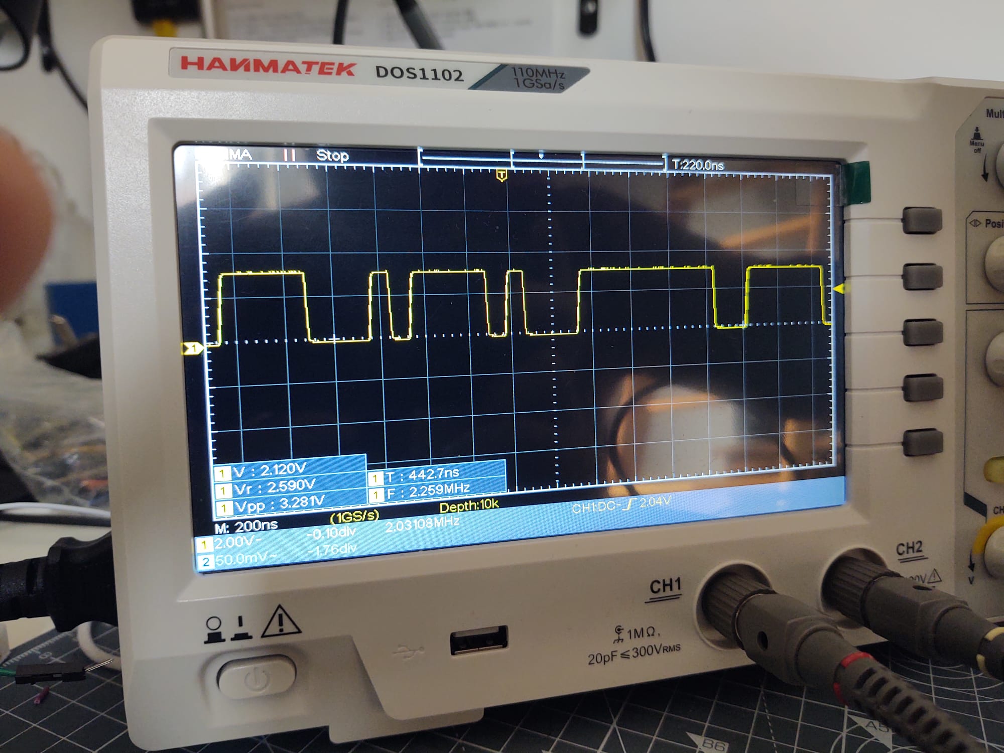
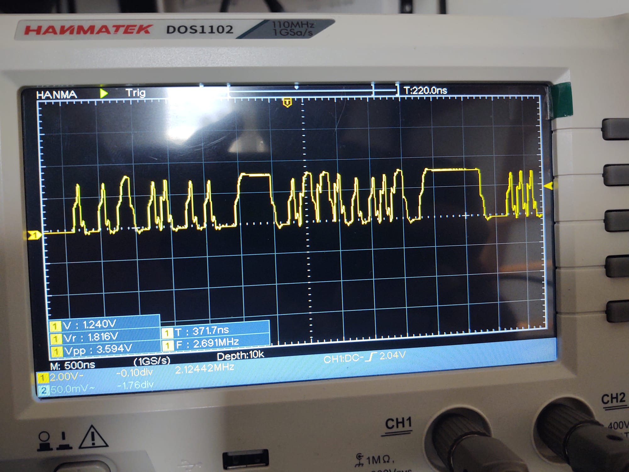
TDM has 3 signals: Frame sync, clock, data.
Digression:
These need to be aligned in time properly. The source emits sync and data on the falling edge of clock, and the receiver samples sync and data on the rising edge of clock.
Easy mode: source-synchronous, with clock and data generated in the same device, then both are sent through the cable. They will arrive at the receiver with correct alignment.
Hard mode: clock is generated at one end of the cable, but the chip transmitting data is at the other end. There will be a roundtrip delay added to the data (and maybe sync, depending on who generates it). If the cable is long enough this can screw up the timing.
Back on topic
The signal on your scope looks like it was sent through a cable with the wrong termination impedance at the source which means it is not usable.
Here's a sim with a 100 ohms transmission line (like 2 wires next to each other in a ribbon cable) directly connected to the output of a logic gate with a bit too much drive strength. The 22 ohm resistance approximates the driving chip's output impedance.
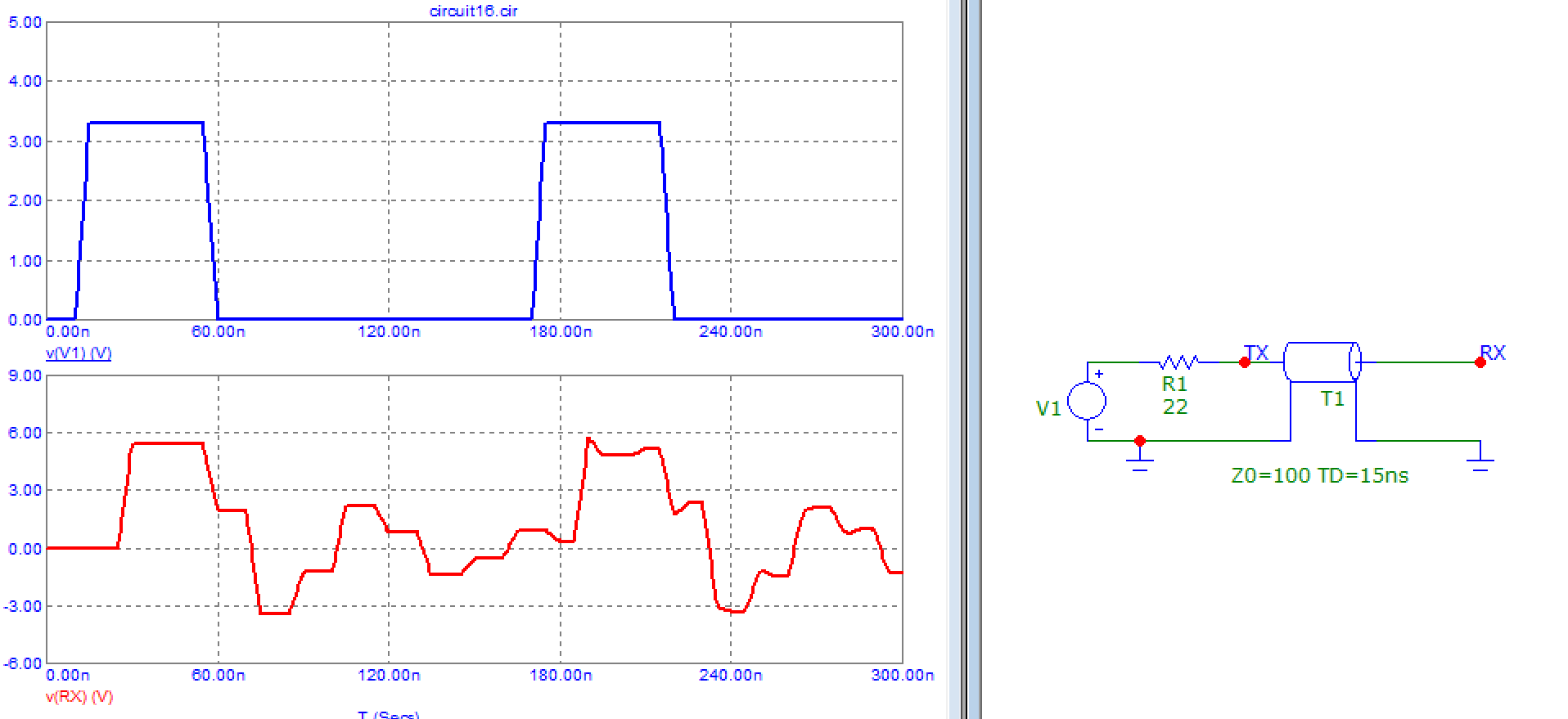
Some of the wiggles are close to logic level "0.5" so you can get double clocking as the input circuit in the receiver interprets it as two clock edges instead of one. In other words it's not working. It's a bad idea to use a circuit at the receiving end to make sense of this signal, the solution is to make sure it arrives in good shape instead.
So you need a clean signal, which means terminating the source of the transmission line at its characteristic impedance:
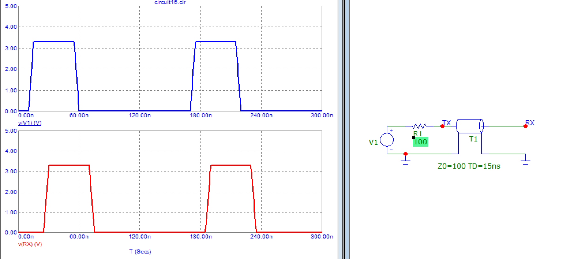
Termination at the receiver is not mandatory. If it is absent, then signal will fully reflect at the receiver, go back through the cable, and be absorbed by the termination resistor at the source.
Termination at both ends works better if the termination resistance does not accurately match transmission line impedance. Here's an example with 80 ohms instead of 100. Termination at both ends delivers a cleaner output, but of course you lose half the amplitude, which is inconvenient with standard logic levels.
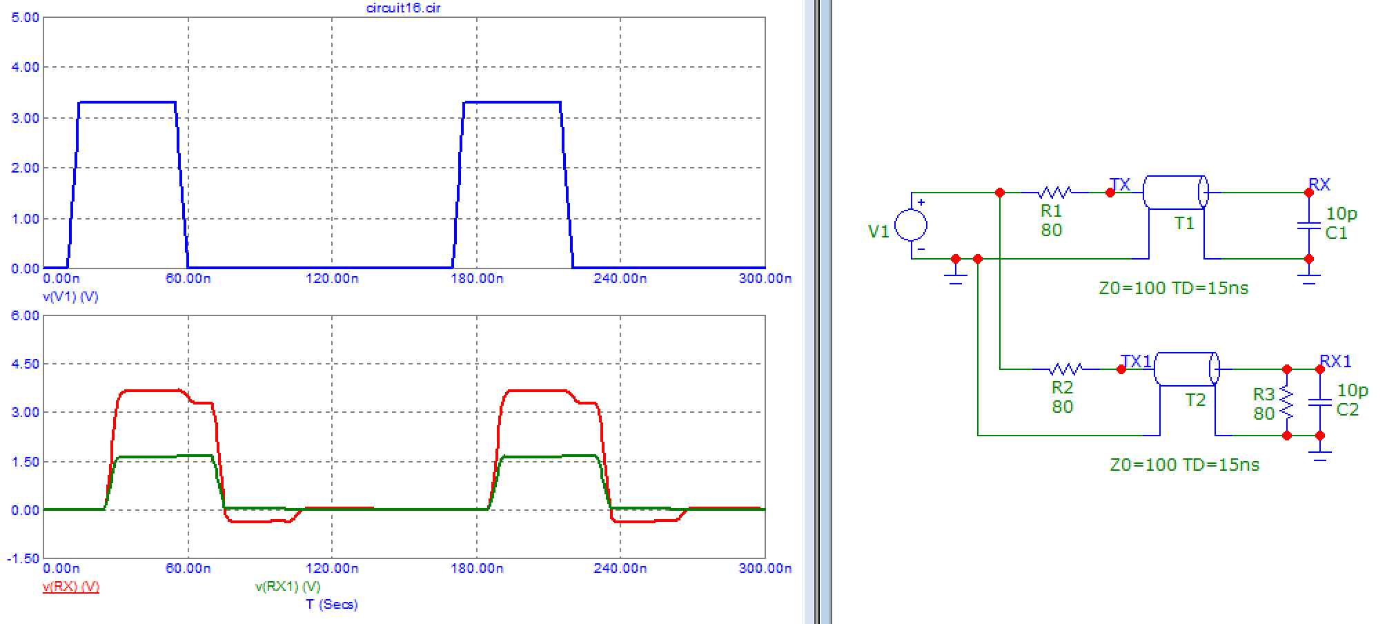
Over 5m with ~5ns edges it means you need a transmission line of known impedance so you can terminate it. Shielding and/or differential is a plus if you don't want to make a wideband radio transmitter. So either a differential signal over twisted pair, or a single ended signal over coax. You could even use ribbon cable, after all PATA did exactly that, but it was inside a shielded computer case so hopefully emissions didn't get out.
Coax is relatively simple, but you need three with assorted connectors, and that's cumbersome. Also propagation delays have to match so the cables should be the same, and you don't have extra pins for power supply and other stuff. Although if you want 3 coax with connectors and extras you can use a VGA cable. Another drawback of single-ended signals is you have to be more careful about EMI and crosstalk through the shared ground.
Fortunately, there's a simple solution: you can either use Cat6 cable for a cheaper option, or an off the shelf HDMI cable which has the advantage of coming readymade with connectors on both ends, a good shield, and plenty of useful extra pins.
Then you can stick a LVCMOS-to-LVDS chip on the sending end, its matching receiver at the other end, decoupling caps, ground plane, and it should work fine.
LVDS allows terminating at both ends without issues about losing half of the logic level 1 voltage, since the receiver is a differential comparator. Just check if the driver and receiver you buy have integrated resistors of the correct value for your cable, or if you have to add them.
