This device has extensive anti-latch-up circuitry, so will not latch-up.
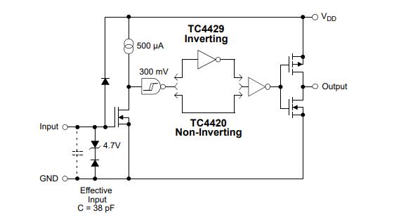
Since the device input is high impedance, the output can be driven high or low depending on external factors associated with the input. Leakage through your high impedance source or leakage through the protection diodes, could be driving the input high or low depending on the source circuitry.
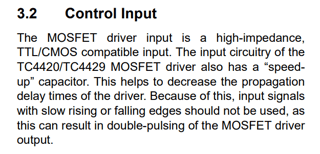
According to the data sheet, the input signal requires short transition times to prevent double-pulsing of the output.
A resistive pull-down will work as long as the fall time meets the requirements from the data sheet.

I could not find in the data sheet what is meant by "slow rise and fall times", but the switching tests were done with input switching times <10ns (Figure 4.1).
The effective input capacitance is 38pF. To first order, the rise/fall time is about 2 time constants. Using 10ns fall time, the time constant is 5ns. So the pull down value is:
$$
R_{pd}=\frac{\tau}{C_{eff}}=\frac{5ns}{38pF}\approx 132\Omega
$$
Higher resistance values may work, but experimantation is required.
Is there a way I could force the driver to (quickly to minimize switching losses) pull its output low when the input signal is in its off stage?
Using a pull-down resistor will minimize the switching losses of the TC4420, but will increase the losses while there is current through the resistor. Much higher power dissipation.
To achieve both reduced power consumption and meet the data sheet specification, a buffer (like the 74LVC1G17) is required between the high impedance source and the TC4420 input. Then a 10kΩ resistor may be sufficient. Of course it will also consume power but maybe less than the resistor pull-down.


