Hello community!
I'm currently working on the design of an ultrasound scanning system, and I'm seeking guidance, particularly in the realm of high frequency PCB design and transmission lines.
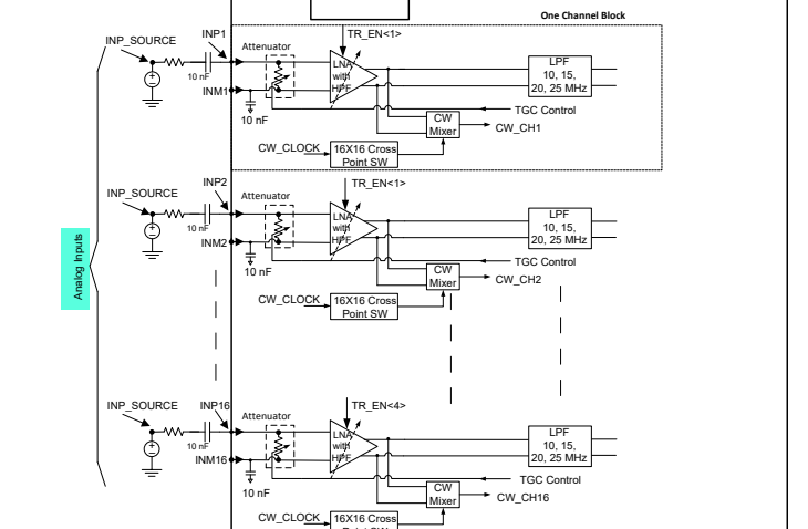
My primary concern revolves around the return signals from the transducer that need to be routed to an Analog Front End (AFE) for filtering and further processing. Considering that ultrasound frequencies typically range from 2 MHz to around 15 MHz, with occasional use of even higher frequencies, Additionally, the data transfer cables back to the PCB can be up to 2 meters, mainly 50-ohm coaxial cables.
Given the low amplitude of the return signals (maxing out at around 2.2V), I'm curious about whether reflections are a common concern at these frequencies. Moreover, I'm contemplating whether matching the impedance of the lines is necessary. If impedance matching is advisable, would placing termination resistors on low-amplitude and low-power lines be a suitable approach?
I appreciate any advice or insights you can provide on these aspects of design. Feel free to share your experiences or suggest resources that might aid me in navigating this aspect of my project.
Thank you!

