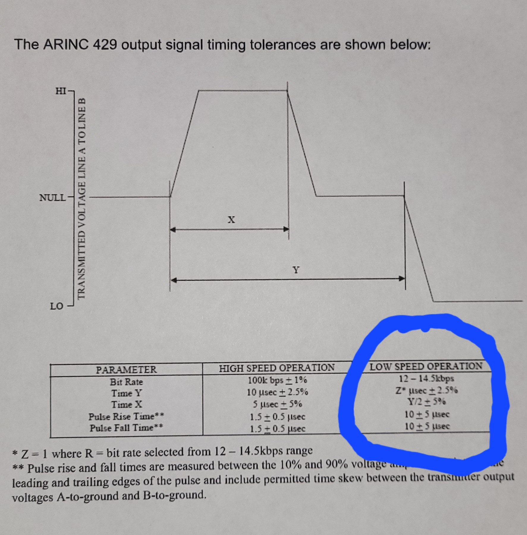
I am using a Raspberry Pi Pico and a few op-amps and resistors to implement an ARINC 429 transmitter. ARINC 429 is a bipolar RZ serial communication protocol commonly used in avionics. See the image below for waveform details (from https://www.altadt.com/wp-content/uploads/dlm_uploads/2013/11/ARINC-Protocol-Summary.pdf).
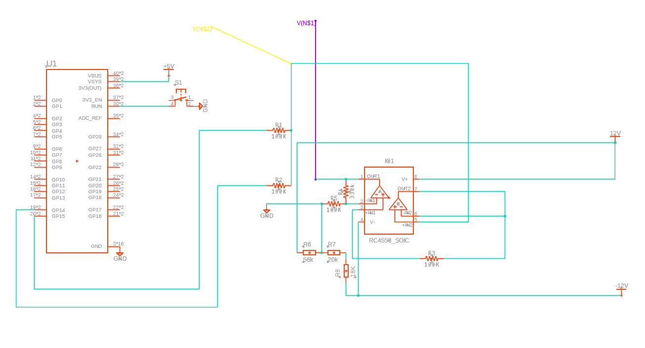
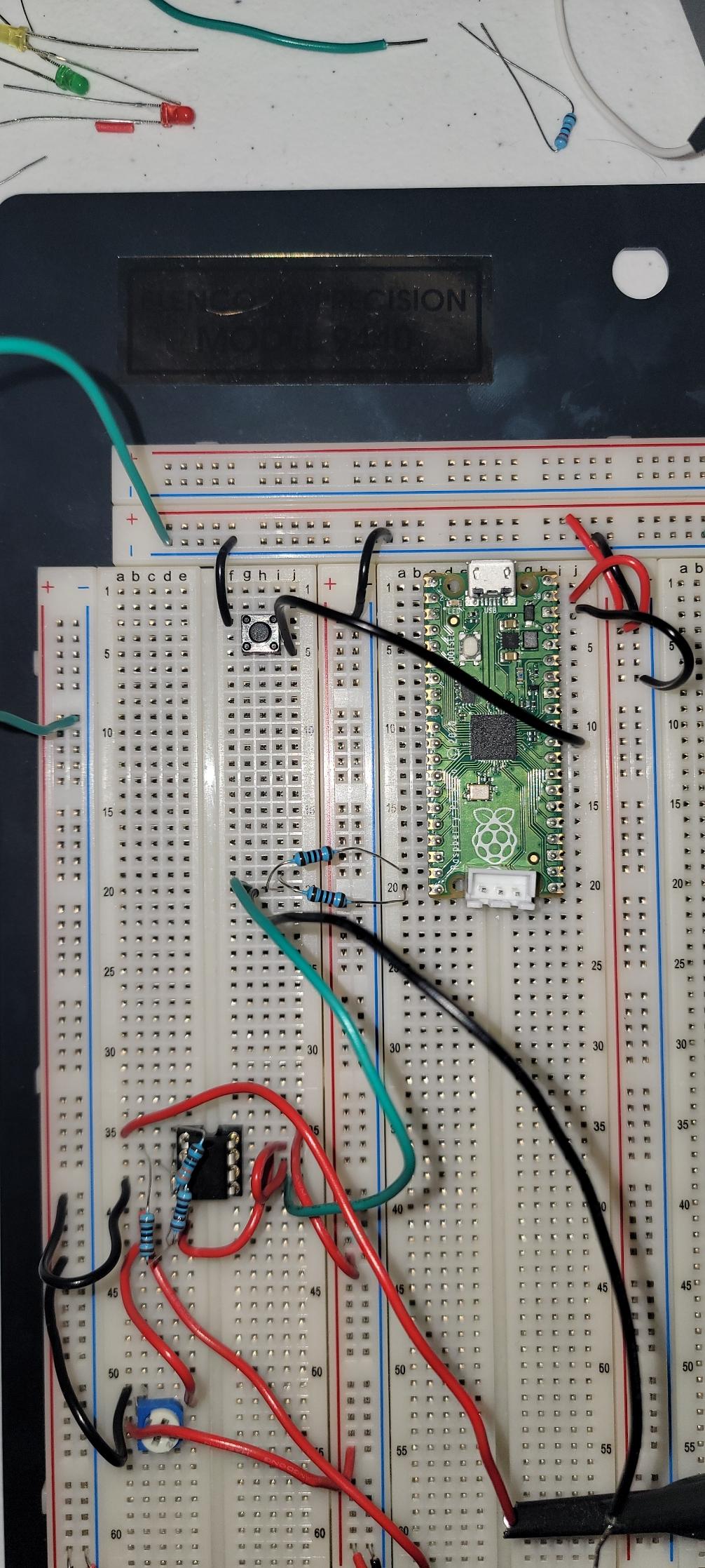
Right now I am just trying to implement the low-speed waveform (12-14.5 kbps circled in blue) but eventually will implement the high-speed waveform as well. I've successfully created the waveform except for the ramped rising and falling edges using the circuit below
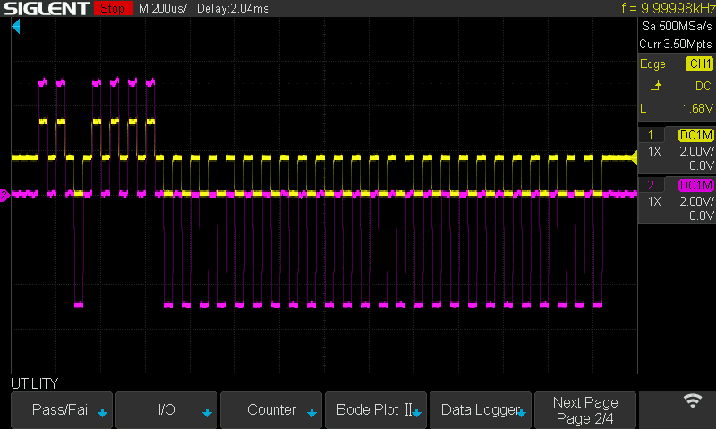
R1 & R2 act as a voltage divider to correctly form the RZ waveform but shifted by +1.65v due to the Pico's digital output voltage of 3.3v. Op-Amp B is a simple non-inverting buffer. Opa-Amp A amplifies (non-inverting) and offsets the signal to the requisite +-5v. R4 & R5 set the gain. R3, R6, R7 & R8 (voltage divider) set the offset to zero volts for the RZ. R6, R7, and R8 are actually a single potentiometer for prototyping purposes on the breadboard. The yellow and red V(N$2) & V(N$1) correspond to the like-colored oscilloscope traces in the images below.
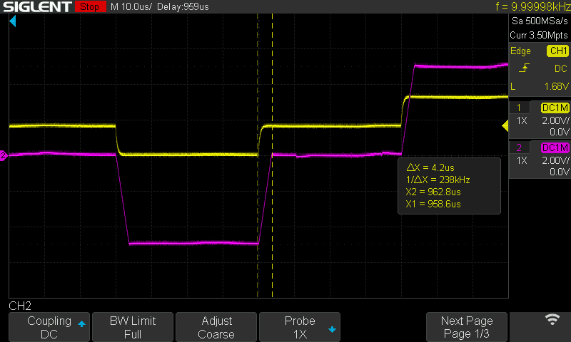
The op-amps' slew rate gets me close to the solution but it's a bit too fast to create the requisite 10μs rise and fall time. You can see this in the oscilloscope screenshots below. The yellow trace is the raw waveform immediately after the voltage divider coming from the Pico's GPIO pins 14 & 15. The purple trace is coming from the output of the second op-amp (Op-Amp B in the schematic)
I tried looking for slower op-amps with no luck and this also seems like a pretty hacky way to accomplish the desired waveform and would require different op-amps for the high-speed waveform.
If anyone has a recommendation on how to accomplish the required rise and fall ramping to meet the 10μs slow-speed and 1.5μs high-speed requirements I would be hugely appreciative.
Update:
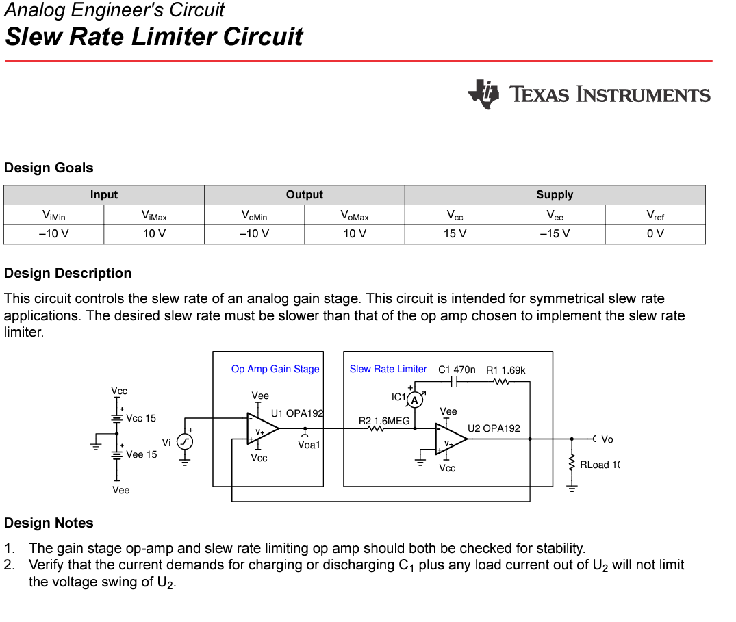
I was able to rebuild the circuit to use the Slew Rate Limiter Circuit from https://www.ti.com/lit/an/sboa218a/sboa218a.pdf, as suggested by Tim Williams. See below for th circuit from Texas Instruments:
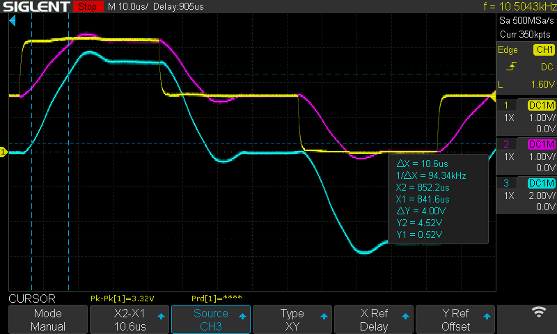
The updated circuit uses the slew rate limiter circuit to accomplish the lower slew rate and then uses a non-inverting op-amp circuit to amplify and offset the resulting signal to +-5v. As you can see from the oscilloscope image below, the slew rate timing is now within the ARINC 429 spec for the low-speed bit rate (I still need to implement high-speed), but the ramped signal overshoots the targe voltage slightly.
I'm not sure if this overshoot is consequential but if anyone has suggestiohns on how to correct this or on a better approach I would really appreciate it.
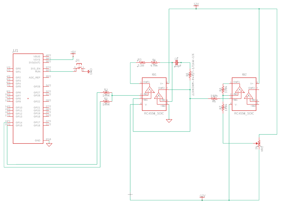
The new circuit design is shown below.
R3, R4, & C1 limit the slew rate, R5 compensates the feedback network for stability. THe third Op-Amp is a simple non-inverting amplifier with VR1 used to adjust the offstet to 0 (+-5v for high and low bits).
Any further suggestions are more than welcome.

