0
\$\begingroup\$

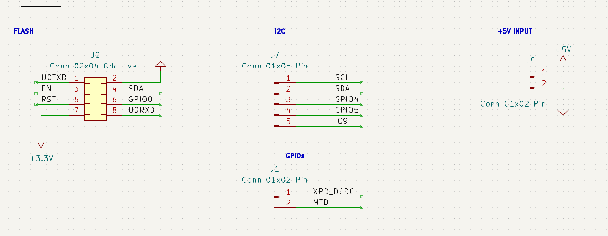
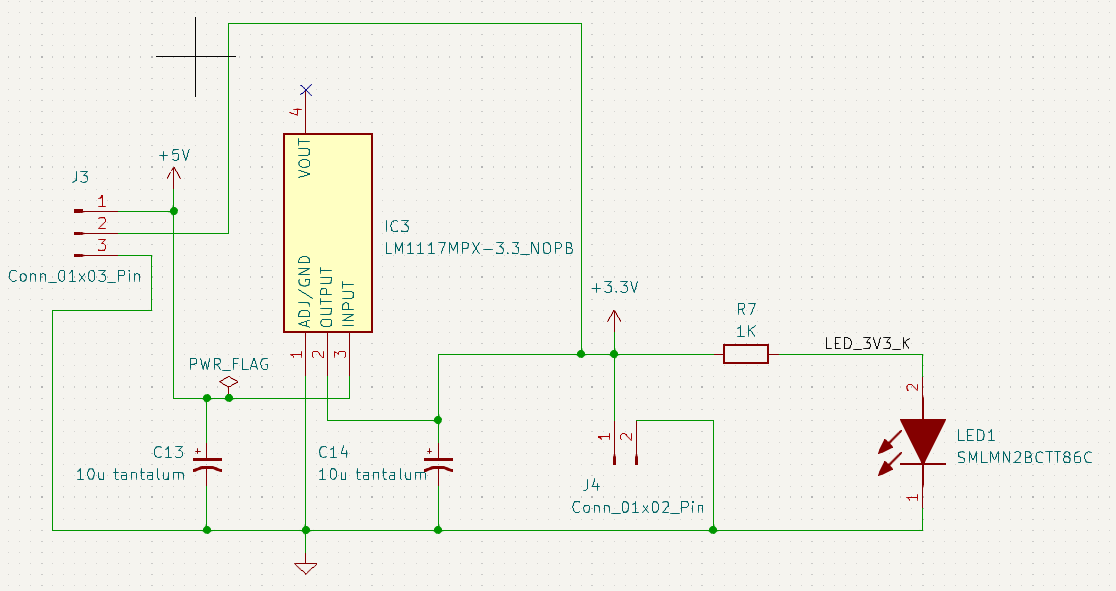
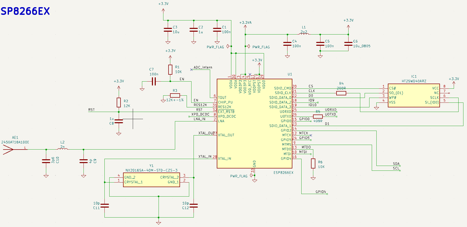
I designed a PCB based on the ESP8266EX dotn here is the schematic:

enter image description here enter image description here enter image description here

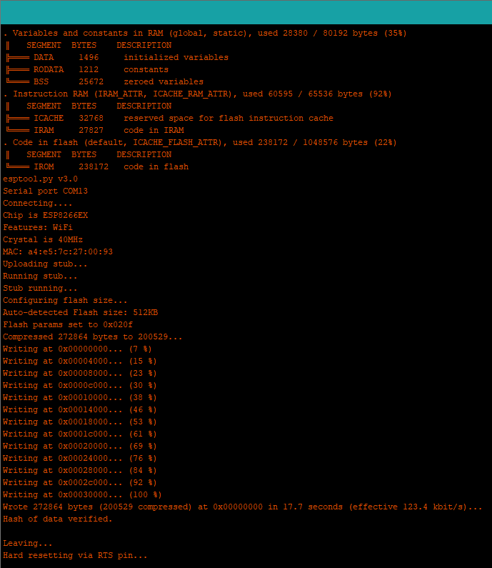
To flash the board I use the module: https://joy-it.net/de/products/SBC-ESP8266-PROG I am able to flash the board with Arduino IDE with a simple code:

void setup() {
  // put your setup code here, to run once:
  Serial.begin(9600);
  Serial.println("OK");
}

void loop() {
  // put your main code here, to run repeatedly:
  Serial.println("OK");
  delay(1000);
}

enter image description here

But when I open the serial monitor, nothing happens.

All the pins of the 8-pin connector are connected respectively to the Joy-it module.

Flash configuration :

  • Card Type: Generic ESP8266 Module"
  • Upload Speed: "57600
  • CPU Frequency: "160 MHz
  • Crystal Frequency: "40 MHz
  • Flash Size: "4MB (FS:3MB OTA:~512KB)"
  • Flash Mode: "DIO"
  • Flash Frequency

I've tried different flash configurations without success.

I wonder if it's a connection problem between CHIP_EN and RST pin.

Flash datasheets: https://datasheet.lcsc.com/lcsc/2201121400_HTCSEMI-HT25WD40ARZ_C2928800.pdf

ESP8266EX datasheet: https://www.espressif.com/sites/default/files/documentation/0a-esp8266ex_datasheet_en.pdf

\$\endgroup\$
2
  • \$\begingroup\$ What if you manually reset it after flashing? What about blinking an LED? \$\endgroup\$
    – StarCat
    Commented Dec 7, 2023 at 15:57
  • \$\begingroup\$ How do you manually reset the esp after flashing? \$\endgroup\$
    – Juno
    Commented Dec 7, 2023 at 20:33

2 Answers 2

0
\$\begingroup\$

Since you can upload the code, many things are going right. I can suggest the following:

  1. Check the GPIO0 pin if it becomes high after you upload the code. If not, try to pull it up using an external 10K resistor. Verify at the ESP pin if the pin is actually going HIGH or not.

  2. I am wondering if the programmer is interfering somehow. Try disconnecting the programmer once you are done. Use a regular USB-UART module and make GND, TX and RX connections to the ESP. See if that works. Probably using a simpler code (led blink) as suggested by starcat in the comments can help you debug it easily.

  3. Check if the crystal is working fine. Whether the part number is correct, soldering is correct, capacitors in the crystal circuit are correct etc.

\$\endgroup\$
0
\$\begingroup\$

Flashing the card in DOUT mode solved the problem

\$\endgroup\$

Your Answer

By clicking “Post Your Answer”, you agree to our terms of service and acknowledge you have read our privacy policy.

Not the answer you're looking for? Browse other questions tagged or ask your own question.