0
\$\begingroup\$

I am trying to simulate a full bridge sensor load cell.

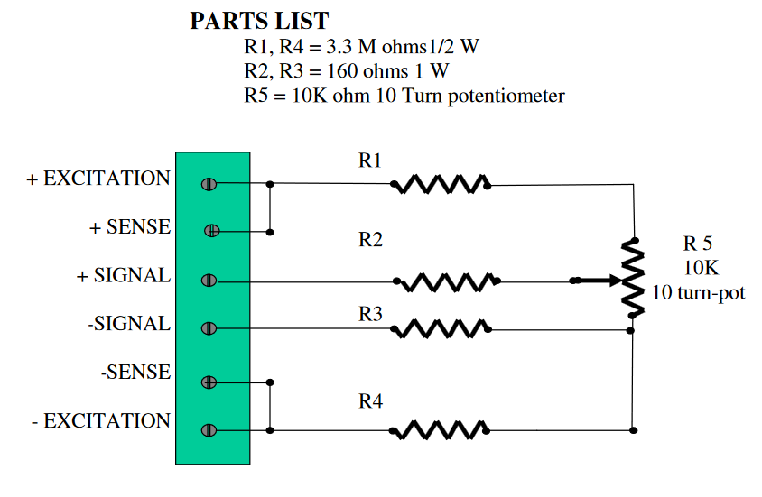
Here is the reff to the image: https://www.scribd.com/doc/140674267/Load-Cell-Simulator-v2

enter image description here

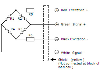
Above is the reff circuit I am using. I know that making a bridge circuit like this one below would work, but I am not able to get the potentiomenter to get the bridge slightly unbalanced (0.1%) so that I can measure a 25mV/volt generated in signal + and signal-.

I built the above circuit, but I didn't have 3.3M in 1/2 watt. I think for this reason changing R5 for the full span is giving just 5mv/volt output. The excitation voltage is 5volt.

Can anyone help me generate 25mv/volt output from the circuit?

Image Reff:https://www.engineeringclicks.com/wheatstone-bridge/

enter image description here

\$\endgroup\$
3
  • \$\begingroup\$ Altroz - Hi, Please note that when a post copies or adapts material (e.g. text, image, photo etc.) from elsewhere, that content must be correctly referenced. For online content, the source webpage / PDF / video etc. should be named & linked as a minimum (see the rule about references for offline books / articles). Therefore please edit your question to add the appropriate source references (source name & link) for each copied image & remember to include references in future. Thanks. || As you're new here, please see the main site rules in the tour & help center. \$\endgroup\$
    – SamGibson
    Commented Dec 7, 2023 at 15:46
  • \$\begingroup\$ @SamGibson I have updated the question \$\endgroup\$
    – Altroz
    Commented Dec 7, 2023 at 15:53
  • \$\begingroup\$ Altroz - Thanks for the first link; although that site is tricky to use, I see that image there. However I looked at the second page you linked, and the second image is not shown on that page. Please check and provide the correct source link for that second image. Thanks. \$\endgroup\$
    – SamGibson
    Commented Dec 9, 2023 at 4:55

1 Answer 1

1
\$\begingroup\$

I suggest you use much lower value precision resistors for R1/R4 and shunt the pot element with a low value precision resistor.

For example, if you use 10kΩ 1% resistors then to get 125mV across the pot (current of 4.875V/20kΩ = 0.244mA) you'd need a shunt resistor of about 540Ω. 549Ω 1% is a standard E96 series value. This is just calculated from Ohm's law, and you can do the same if you want a different voltage span.

\$\endgroup\$
2
  • \$\begingroup\$ i dont think my issue is tha span, i need to het 25 Mv at the output of signal + and - \$\endgroup\$
    – Altroz
    Commented Dec 7, 2023 at 17:05
  • \$\begingroup\$ This will give you 0 to 125mV (polarity depends on which way it is connected). So 25mV/V as you requested. \$\endgroup\$ Commented Dec 7, 2023 at 17:13

Your Answer

By clicking “Post Your Answer”, you agree to our terms of service and acknowledge you have read our privacy policy.

Not the answer you're looking for? Browse other questions tagged or ask your own question.