0
\$\begingroup\$

Please help me understand this PRC circuit of a SMPS.

According to the NCP1606 PFC controller datasheet pin 4 is responsible for current sensing. Now, there are two resistors:

(red) in series to the source of the MOSFET source pin and

(blue) connected to ground.

At first I was not sure which of the two are serve for current sensing. Usually I follow two indicators to determine whether a resistor is a current sense resistor:

  1. The resistor is in series with the load or
  2. The resistor has a very low ohm value.

With the help of the example circuit on page 1 of the datasheet, I can say that the resistor connected to the ground plane is the current sense resistor. How would I could I determine the current sense resistor if I had no example circuit on hand?

Does the low ohm value trump the 'in series with load' argument?

My second question: what is the purpose of the red resistor? Would be safe to assume that it limits current?

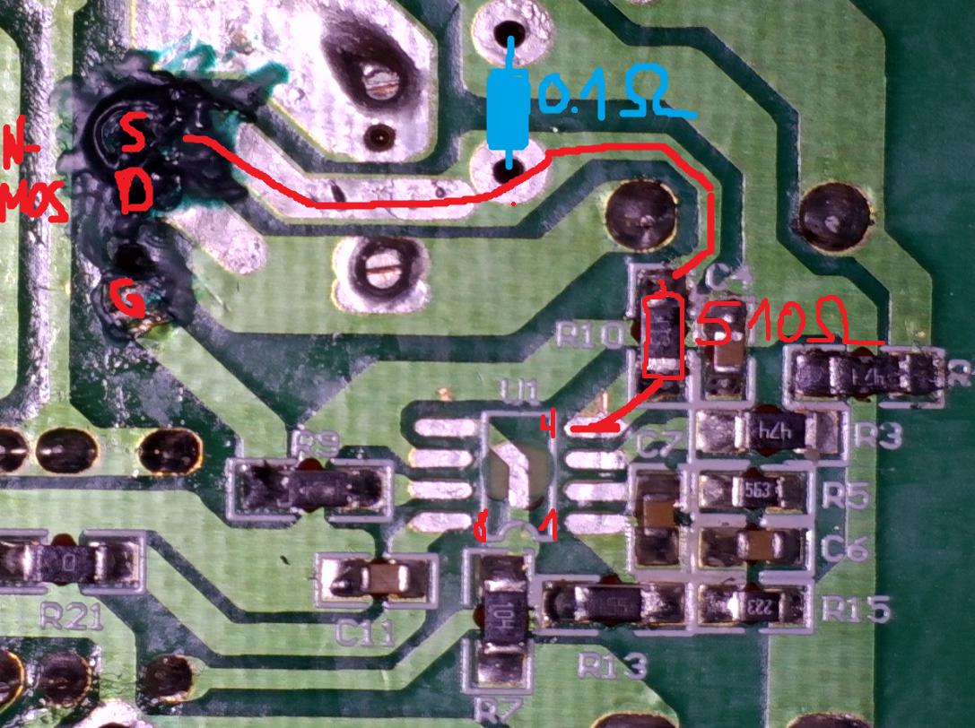
PFC circuit

\$\endgroup\$
3
  • 5
    \$\begingroup\$ The "blue" one is the true current-sense resistor. The "red" is likely there for form a small filter with the CS pin capacitance unless there is a small cap. connected between CS and GND which will strengthen the filter effect. The 1606 is a constant on-time borderline PFC whose power depends on the capacitor connected at pin \$C_t\$. The sense resistor is there for cycle-by-cycle protection. \$\endgroup\$ Commented Dec 8, 2023 at 19:40
  • 1
    \$\begingroup\$ @VerbalKint you should put it as an answer. \$\endgroup\$ Commented Dec 8, 2023 at 21:00
  • \$\begingroup\$ Will do tomorrow! : ) Thanks Rohat. \$\endgroup\$ Commented Dec 8, 2023 at 21:50

1 Answer 1

3
\$\begingroup\$

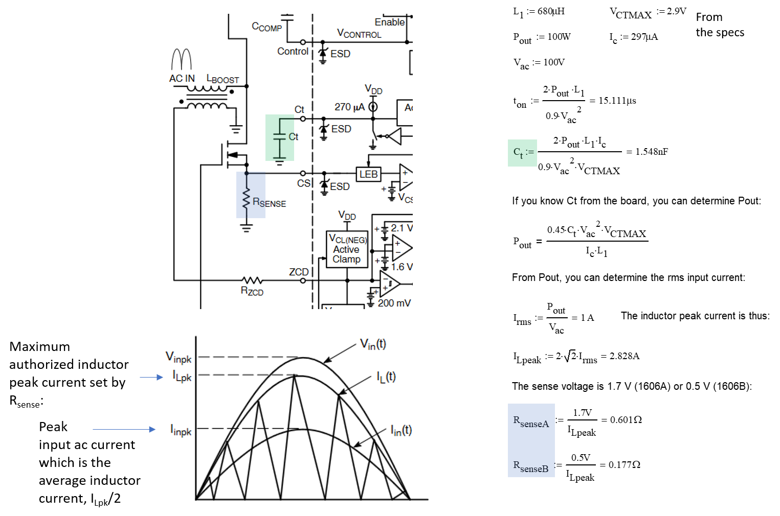
The NCP1606 is a constant on-time PFC controller operating in borderline conduction mode or BCM. There is no voltage sensing as in its current-mode version like the old MC33262 for instance. Capacitor \$C_t\$ sets the on-time that you will determine based on the transmitted power and inductance value. Assume the following values:

enter image description here

By measuring the inductance and the \$C_t\$ value, you will determine the nominal power of the board and then progress to the sense resistance value. That is the way I would do but there are probably different options also. Please check whether the original controller was a A or B version as the sensed voltage differs between the two parts.

The small resistance in series with the CS pin can be combined with a capacitor of a few tens of pF to form a low-pass filter, helping the internal leading-edge blanking (LEB) circuit included in the IC. It is good practice to keep this filter in place, with the \$RC\$ elements colocated with the controller.

\$\endgroup\$

Your Answer

By clicking “Post Your Answer”, you agree to our terms of service and acknowledge you have read our privacy policy.

Not the answer you're looking for? Browse other questions tagged or ask your own question.