1
\$\begingroup\$

I have been looking into differential amplifier circuits, differential input impedance, and common-mode input impedance.

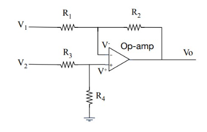
Everywhere I go (such as here or here), I see this as the solution for differential amplifier inputs,

enter image description here

R1+R3 for differential input impedance, R3+R4 for common-mode input impedance.

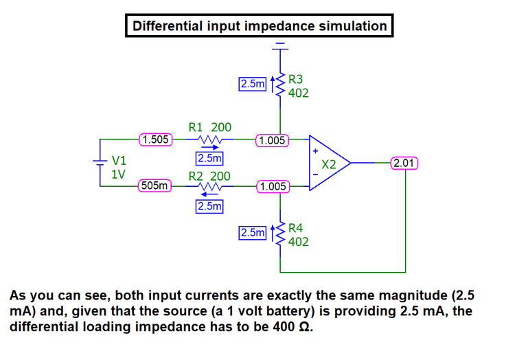
For differential input impedance, many of them offer a surface level explanation revolving around +ve and -ve terminals being equal to each other, and the terminals being assumed to be connected by the same voltage source but one on the +ve side and one on the -ve side. Per my understanding, differential input impedance is used when the inputs are different in polarity (one +ve, one -ve) but I don't understand how that results in the aforementioned input impedance.
enter image description here (Picture from here)

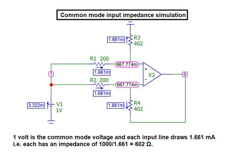
For common-mode input impedance, it seems to assume both terminals as having identical inputs, but I fail to understand anything that happens after. Per my understanding, common-mode input impedance is used when the inputs are identical in polarity (both +ve or both -ve) but I also don't understand how that results in the aforementioned input impedance.

enter image description here

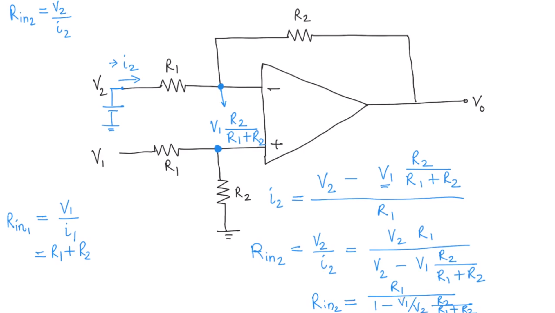
I also found one deviation from the norm: this video, which states the input resistance (not specified what type) as the following:

enter image description here

I would like to know how these assumptions are made, and (more importantly) how these input impedance values are derived. Please let me know if more information is required.

\$\endgroup\$
1
  • \$\begingroup\$ I recognize the diagrams in your question. Maybe you should attribute them. \$\endgroup\$
    – Andy aka
    Commented Dec 17, 2023 at 16:56

1 Answer 1

1
\$\begingroup\$

Your first assumption is incorrect. The differential inputs don't need to have different polarity. You just have a voltage difference of 1V between the input. And since the op-amp is assumed ideal, it has no limitations and through feedback it is guaranteed that op-amp inverting and non-inverting input are at the same voltage. So your schematic proves that op-amp functions and you get differential input impedance of 1V/2.5mA which equals 400 ohms, and that's because there is 1V over the 400 ohms of R1+R3 is 400 ohms like in the text below the picture.

For the common mode case, same applies, except now there is 0V between the inputs, and both inputs are at 1V. The op-amp inputs still must be at equal voltage because of feedback. So there must be 604 ohms with 1V over it. Both from non-inverting input to ground, and from inverting input to output. As they must be equal it means op-amp output must be 0V.

So it all boils down to so called golden rules of (ideal) op-amps. Output does everything it must do to keep inputs at equal voltage. No current flows in or out of op-amp input terminals. There's more but those two are the only ones you need to solve these circuits using simply Ohm's law.

\$\endgroup\$
7
  • \$\begingroup\$ Thank you. So, say I have two 2.5V sine waves 180 degrees out of sync, with an amplitude of 1V. Is the common-mode voltage the 2.5V element and is the differential voltage the 1V element? \$\endgroup\$ Commented Dec 14, 2023 at 23:55
  • \$\begingroup\$ I'm also not sure how to get from "And since the op-amp is assumed ideal, it has no limitations and through feedback it is guaranteed that op-amp inverting and non-inverting input are at the same voltage." to "So your schematic proves that op-amp functions and you get differential input impedance of 1V/2.5mA which equals 400 ohms" I see the simulation proving it, but I don't quite understand the theory behind it. \$\endgroup\$ Commented Dec 14, 2023 at 23:57
  • \$\begingroup\$ @HFOrangefish I'd say you cannot have a 2.5V sine wave with amplitude of 1V if you already defined the amplitude to be 2.5V. \$\endgroup\$
    – Justme
    Commented Dec 14, 2023 at 23:57
  • \$\begingroup\$ My bad, I meant a 1V amplitude sine wave with an offset of 2.5V. \$\endgroup\$ Commented Dec 14, 2023 at 23:59
  • 1
    \$\begingroup\$ @HFOrangefish Yes for two 1V sine waves with 2.5V offset, the offset is the CM voltage, and difference between them will be +2 to -2 volts. \$\endgroup\$
    – Justme
    Commented Dec 15, 2023 at 0:03

Your Answer

By clicking “Post Your Answer”, you agree to our terms of service and acknowledge you have read our privacy policy.

Not the answer you're looking for? Browse other questions tagged or ask your own question.