1
\$\begingroup\$

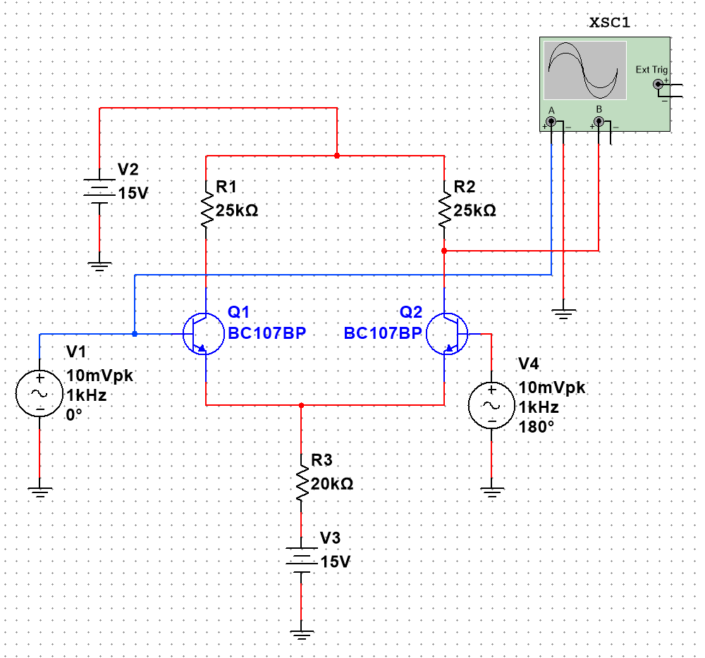
Maybe someone can help and knows how to calculate the differential gain and common-mode gain in a differential amplifier. Will the formula for differential gain be Ad=Rc/2Re, i.e. in my case 50/40=1.25? I don't know how to calculate the total.

Can this be measured in Multisim?

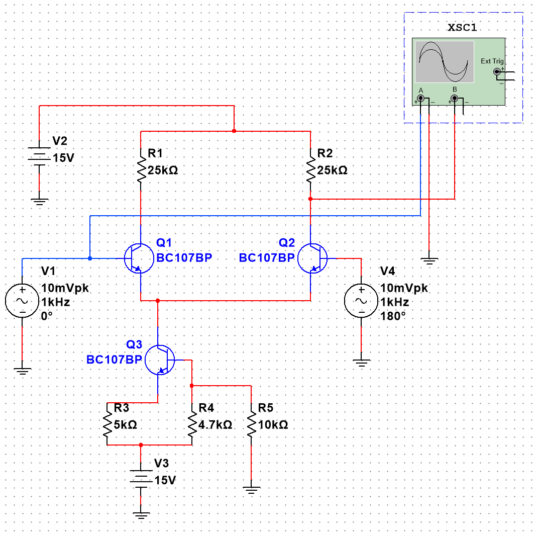
Diagram with parameters in the photo.

First diagram

Second diagram in which a current source was used

\$\endgroup\$
6
  • \$\begingroup\$ Are you asking for theory and how to calculate things? If so, just simplified theory using a simple linearization around an operating point? Or large scale theory that illustrates the arctan behavior more fully? Or are you asking for a complete schematic testbed that you can use for simulation purposes in order to extract numerical values? \$\endgroup\$ Commented Dec 15, 2023 at 19:18
  • \$\begingroup\$ I would like to know what formulas to use and which values to substitute (values from the attached diagrams) to calculate it correctly. \$\endgroup\$
    – grigoriii
    Commented Dec 15, 2023 at 19:21
  • \$\begingroup\$ Please consider reading this. \$\endgroup\$ Commented Dec 15, 2023 at 19:30
  • \$\begingroup\$ V3 should be -15V \$\endgroup\$
    – user319836
    Commented Dec 16, 2023 at 0:01
  • \$\begingroup\$ Ok, You right V3 is now reversed. But my osciloscope show: image Is this correct?, or shouldn't it show a second wave. Am I missing something in the multisim? \$\endgroup\$
    – grigoriii
    Commented Dec 16, 2023 at 11:28

1 Answer 1

0
\$\begingroup\$
  • The so-called "differential gain Vd" is based on the assumption that Vin1=-Vin2. Therefore, the current increase in Q1 is identical to the current decrease in Q2. As a result, the current through the common emitter node remains constant and we can treat this node as signal ground. That means: The gain Vd (referenced to one collector output) is identical to the gain of a simple common-emitter gain stage without feedback:

    Vd=(+ -)gm*Rc (gm: transconductance; gm=Ic/Vt).

  • In case of common-mode operation in both transistors the current increase (resp. decrease) is identical. So this current increase causes a feedback voltage across the resistance in the common emitter leg (static Re, or dynamic re when there is a 3rd transistor). Without additional calculations, we can use the known gain expression for a common-emitter stage with feedback. However, because the current increase/decrease is twice that of a single transistor, the feedback resistor must be doubled in the gain formula:

    Vcm=-gm*Rc/(1+2gmRe)

    (in case of a 3rd transistor replace Re by re (large dynamic transistor ouput resistance)

\$\endgroup\$
2
  • \$\begingroup\$ OK, but i have problem with second circuit (second image), with additional power source. What values to substitute into the formula to calculate it? \$\endgroup\$
    – grigoriii
    Commented Dec 18, 2023 at 6:47
  • \$\begingroup\$ As I have mentioned in my answer: Replace Re by a "dynamic re when there is a 3rd transistor". This is the large output resistance (often called "ro") of the 3rd transistor. \$\endgroup\$
    – LvW
    Commented Dec 18, 2023 at 8:09

Your Answer

By clicking “Post Your Answer”, you agree to our terms of service and acknowledge you have read our privacy policy.

Not the answer you're looking for? Browse other questions tagged or ask your own question.