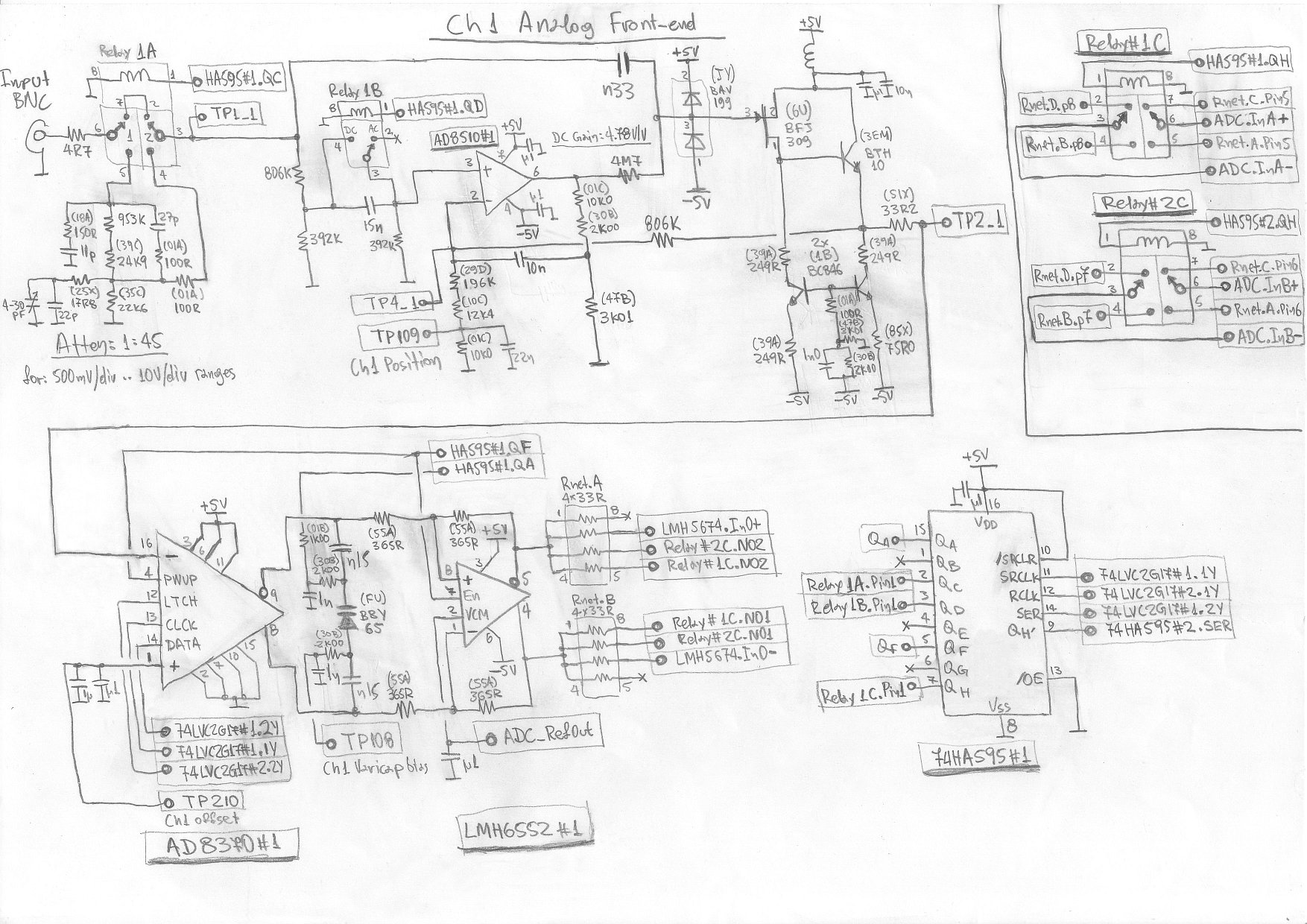
The analog front end of an oscilloscope begins with an attenuation stage. Mostly they use two attenuation stages, like 1/1 and 1/50.
 From: Rigol Homebrew Wiki - schematics page
The image above belongs to an oscilloscope AFE. Here, a relay sets the attenuation. The attenuation is in the stage of 1/1 in the picture. After the relay and a 330 pF capacitor there is a clipper diode stage.
When the frequency increases, the reactance of the capacitor decreases. When a 50 MHz signal is applied the reactance is 9.64 Ω.
How can clippers stands a 20 Vpp, high-current, 50 MHz signal? What is protecting the +5 V and -5 V lines from the input signal? And how does this protect semiconductors?
