0
\$\begingroup\$

For the past few days, I've been going in circles trying to plan a circuit to detect water between a pair of metal probes (or more precisely, between several pairs of stainless steel probes approximately 1 inch apart connected in parallel, and two "water sensor" circuit boards that consist of two zig-zagging 50-mil traces separated by 50-mil space).

The fundamental problem is, I don't really understand the finer points of Ohm's Law (or at least, the parts that might deviate from what I suspect is actually a simplified special case... when you aren't just talking about a simple resistor limiting current between +3.3v and ground).

Consider the following circuit (in series), using a 3.3v ESP32:

  • GPIO pin that's normally left floating as an input (to minimize galvanic corrosion of the probes), but configured for output & taken high (to 3.3v) shortly before triggering ADC conversion.

  • 82-100 ohm resistor (to limit the maximum possible current flowing between the GPIO and ADC pins to 40mA or less, even if there ends up being a dead short and zero ohms between the probes

  • a pair of probes (normally, with air insulating them... potentially, with tap water insulating them a bit less)... and two or more such pairs connected in parallel (so there could be current flowing between none of them, between one pair, or between multiple pairs)

  • ADC input pin on the ESP32

The things that have me scratching my head:

  • If you assume 3.3v on the GPIO pin and only 82 ohms between it and the ADC pin, how many volts will the ADC sense/measure/see?

  • Does a 12-bit ADC actually have enough "headroom" to meaningfully sense the difference between all-but-infinite resistance (82 ohms + an inch of open air) and whatever resistance you'd likely encounter between two stainless-steel probes immersed in tap water? Or at best, would you end up with readings that just jittered between something like 0 to 5 and 2 to 7 (out of 4095), and were so close and mostly-overlapping, you almost might as well randomly flip a coin to decide whether or not there's water present?

I suspect that the impedance of the ADC itself is an important detail that I don't know the value of.

I'm kind of embarrassed to be asking this, because this is apparently considered to be an absurdly-simple circuit... but all the examples I've seen basically consist of a voltage comparator whose output directly triggers a piezo, as opposed to using a MCU to measure it through a proper ADC. I'm not sure whether that's because the amount of voltage at the far end would be too low to reliably measure with a 12-bit ADC, or just because prior to just a few years ago, the very idea of using a MCU and ADC for something like this would have been prohibitively expensive overkill (instead of, like, $9 for an ESP32-C3 that you need anyway for the wi-fi link).

Do I actually need to do something like have the ESP32's 3.3v GPIO trigger a MOSFET switching 5.0v, then amplify the other end with an op-amp and/or run it through an optocoupler or something? Or am I way overthinking something that isn't nearly as complicated as I'm making it?

\$\endgroup\$
12
  • \$\begingroup\$ Can you please draw a diagram, a schematic? Because, feeding 3.3V into ADC will make it read 3.3V. Feeding some other voltage makes it read that voltage. Unless impedance is too high and the ADC can't read it. So the ADC by itself cannot measure resistance in any meaningful way, you need to convert your sensor to output voltage. \$\endgroup\$
    – Justme
    Commented Jan 5 at 23:27
  • \$\begingroup\$ What "finer points of Ohm's Law" do you have in mind? For >99% of the cases you will ever encounter, Ohm's Law works exactly as its simple form seems to suggest. \$\endgroup\$
    – TooTea
    Commented Jan 5 at 23:27
  • \$\begingroup\$ @TooTea is right. If you see Ohm's law stops working, it means, whatever you thought was resistance, is not, or at least is not anymore. \$\endgroup\$
    – Justme
    Commented Jan 5 at 23:31
  • \$\begingroup\$ The problem is, I can't figure out what the voltage would be at the ADC end after starting out as 3.3v, passing through an 82-100 ohm resistor, then an inch of water with some presently-unknown but non-infinite resistance. Ohm's law tells me how much current is reaching the ADC, but seemingly says nothing about the voltage drop across the resistor and water-between-the-probes. Every water-detection circuit I've seen uses voltage-comparators, so a voltage drop IS presumably occurring... but I don't understand how to predict how many volts the ADC itself will see. \$\endgroup\$
    – Bitbang3r
    Commented Jan 5 at 23:44
  • \$\begingroup\$ Is this to detect if water is in an area that is normally dry or is the probe(s) immersed in water all the time? If it is immersed in water all the time you will erode one of the electrodes due to electrolytic corrosion. Plus, the resistance reading will change as bubbles form and break off the surface of the electrodes. \$\endgroup\$
    – qrk
    Commented Jan 6 at 0:18

1 Answer 1

1
\$\begingroup\$

If you assume 3.3v on the GPIO pin and only 82 ohms between it and the ADC pin, how many volts will the ADC sense/measure/see?

The 82 Ω to the ADC will form a potential divider with the input impedance of the ADC. I would expect this to be in the order of 100 kΩ to several MΩ. The datasheet should give this value. In any case the if the ratio was 82 Ω : 82 kΩ (1 : 100) the ADC would see 99% of 3.3 V (which is fine). A higher input impedance would improve this further.

Does a 12-bit ADC actually have enough "headroom" to meaningfully sense the difference between all-but-infinite resistance (82 ohms + an inch of open air) and whatever resistance you'd likely encounter between two stainless-steel probes immersed in tap water?

"Headroom" isn't quite the right word as the dry reading will be 100%. "Resolution" or "span" of readings might be better. This would be very easy to test with a 3.3 V supply, your multimeter and test probes. Check the open-circuit voltage (3.3 V) and then apply the various test conditions to your probe while measuring the voltage.

I suspect that you'll find that 82 Ω is quite a stiff pull-up and that a wet probe may struggle to pull the voltage down significantly so be prepared to check with 1 kΩ and 10 kΩ.

Or at best, would you end up with readings that just jittered between something like 0 to 5 and 2 to 7 (out of 4095), ...

More likely > 4000, if anything (he said without doing any tests).

I suspect that the impedance of the ADC itself is an important detail that I don't know the value of.

It will be high relative to what you're measuring so I wouldn't worry about it (unless you end up with very high pull-up resistors). That information must be available from the datasheet?

schematic

simulate this circuit – Schematic created using CircuitLab

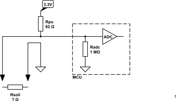
Figure 1. Equivalent circuit. RPU is the pull-up resistor.

So you're saying that the circuit would NOT be, GPIO (outputting 3.3v) -> resistor (limiting current) -> probe -> water -> probe -> ADC pin?

No. That wouldn't work. You want to create a potential divider. The voltage at the ADC input will be

$$ V_{ADC} = 3.3 \frac {R_{SOIL}} {R_{PU} + R_{SOIL}} $$

Now it should be clear that the ADC input impedance makes very little difference to the reading.

\$\endgroup\$
6
  • \$\begingroup\$ Wait, so you're saying that the circuit would NOT be, GPIO (outputting 3.3v) -> resistor (limiting current) -> probe -> water -> probe -> ADC pin? \$\endgroup\$
    – Bitbang3r
    Commented Jan 5 at 23:52
  • \$\begingroup\$ @Bitbang3r That is what I said too. You can't put 0 ohms to say 1 megaohm between 3.3V and ADC input and expect anything else than 3.3V as there is no current and no voltage drop. Basic ohm's law. \$\endgroup\$
    – Justme
    Commented Jan 5 at 23:57
  • \$\begingroup\$ @Bitbang3r: See the update. \$\endgroup\$
    – Transistor
    Commented Jan 6 at 0:10
  • \$\begingroup\$ @Transistor ah, this clarifies things a lot! Thanks! \$\endgroup\$
    – Bitbang3r
    Commented Jan 6 at 0:37
  • \$\begingroup\$ @Bitbang3r, good. Wait a day or two to encourage other responses and then accept the one which best answers your question. Otherwise your question will periodically pop up in the main index as unsolved. \$\endgroup\$
    – Transistor
    Commented Jan 6 at 2:02

Your Answer

By clicking “Post Your Answer”, you agree to our terms of service and acknowledge you have read our privacy policy.

Not the answer you're looking for? Browse other questions tagged or ask your own question.