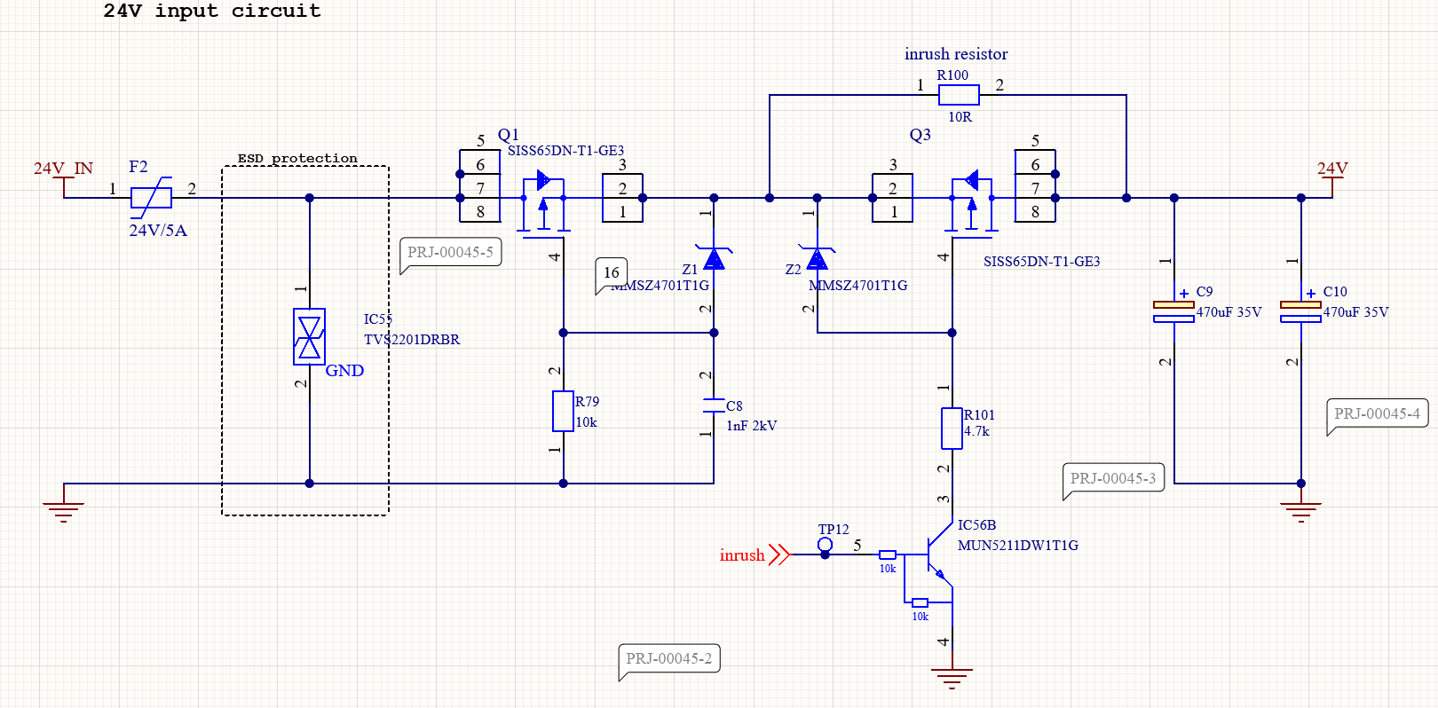
In the development of ESD protection and reverse polarity, I encountered a problem. The circuit is supposed to prevent reverse polarity (it does, we tested it).
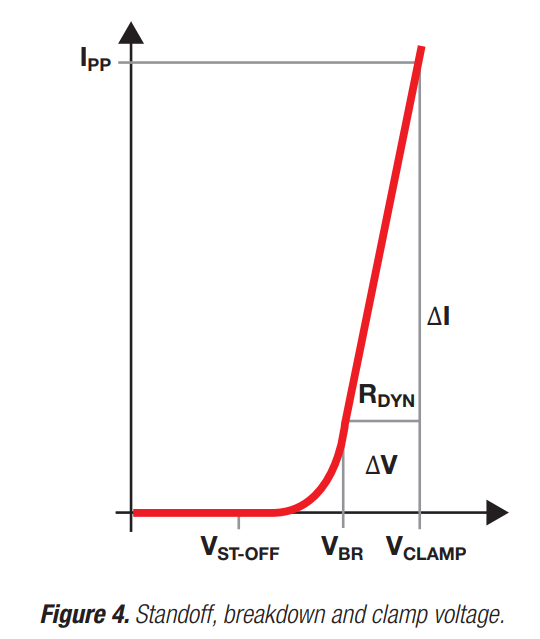
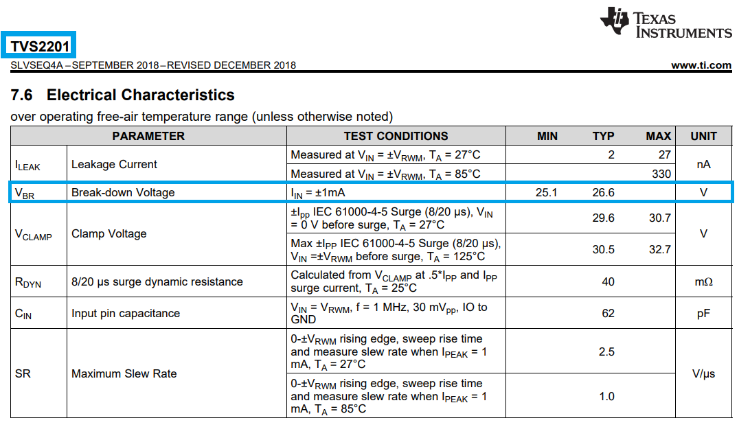
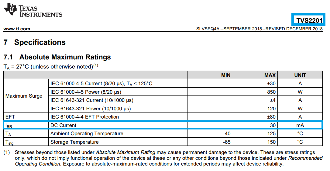
During testing, I applied a voltage of 27 V (it is designed for 24 V input voltage) to the input (used power supply: MPS-3005L-3MATRIX). Looking at the documentation of the TVS diode itself: TVS2201 Datasheet, the diodes start clamping at 29.6 V, and the standoff voltage is approximately ±22 V.
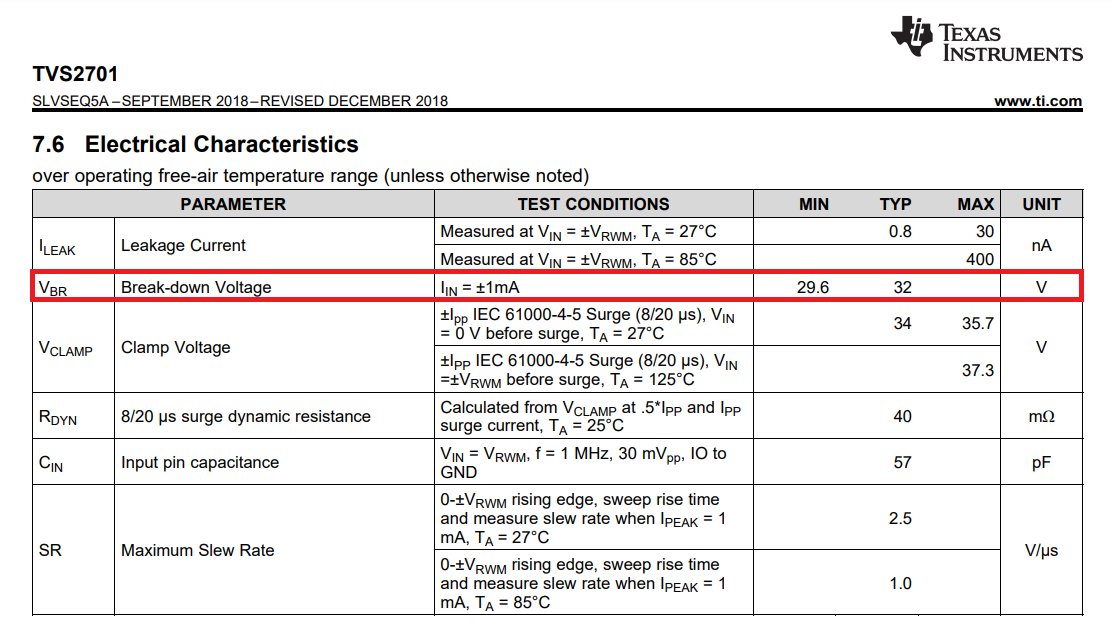
In the actual design, I made a mistake by using the 2201 diode instead of the 2701, but this led to the problem. The diode failed at 27 V and then began conducting 2 A. The inrush resistor heated up, and the diode as well, indicating a short circuit or damage. The PCB design itself is in accordance with the datasheet. I am attaching the schematic.
In the corrected design, we will choose the 2701 diode, as originally intended in the initial design. However, from the perspective of preventing a short circuit in production, I am a bit concerned about the conduction of the diode at around 27 V input voltage.
Does anyone have any idea why this happened with such a low voltage, and has anyone else experienced this before?

