efforts noted
Your first post shows a lot of supplies, parts, and solderless breadboards in use. Your second post writes: "I am required to use sequential circuits and combinational circuits only for this project." This tells me you are involved in related classwork, so not only trying to build something but also studying how to design what you may later build. This latest question now extends on the prior two, showing you are trying to acquire a specific set of useful mental tools related directly to these kinds of activities. Looks like significant effort, to me.
(In the following, I'm borrowing table work from here to save time.)
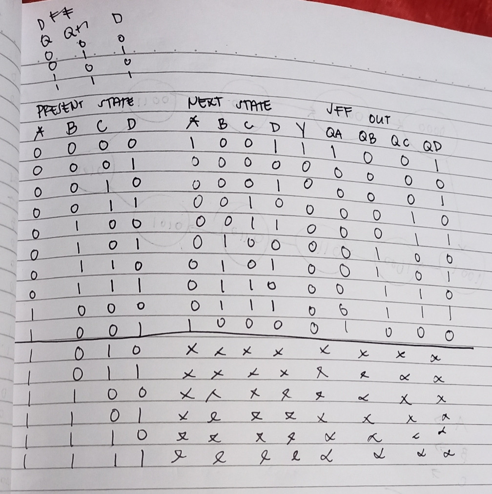
FF options
Unless homework specifically limits choices, please keep in mind there are at least these options for FFs:
$$\begin{array}{c|c|c}
\text{Transition} & \text{JK FF} & \text{T FF} & \text{D FF}\\\hline
{\begin{smallmatrix}\begin{array}{c}
\text{start }\to\text{ end}\\\\
0 \quad \to \quad 0\\
1 \quad \to \quad 1\\
0 \quad \to \quad 1\\
1 \quad \to \quad 0
\end{array}\end{smallmatrix}} &
{\begin{smallmatrix}\begin{array}{cc}
J & K \\\\
0&x\\
x&0\\
1&x\\
x&1
\end{array}\end{smallmatrix}} &
{\begin{smallmatrix}\begin{array}{c}
T\\\\
0\\
0\\
1\\
1
\end{array}\end{smallmatrix}} &
{\begin{smallmatrix}\begin{array}{c}
D\\\\
0\\
1\\
1\\
0
\end{array}\end{smallmatrix}}
\end{array}$$
The D column is obvious. Just present the next state you want before clocking. T FFs are readily made from JK types (just wire the J and K inputs together.) The JK often offers the least complicated surrounding combinatorial logic for desired state transitions. But not always. It doesn't hurt to keep all options on the table when using a simulator. Otherwise, obey physical reality (7400 family) or virtual reality (homework limits.)
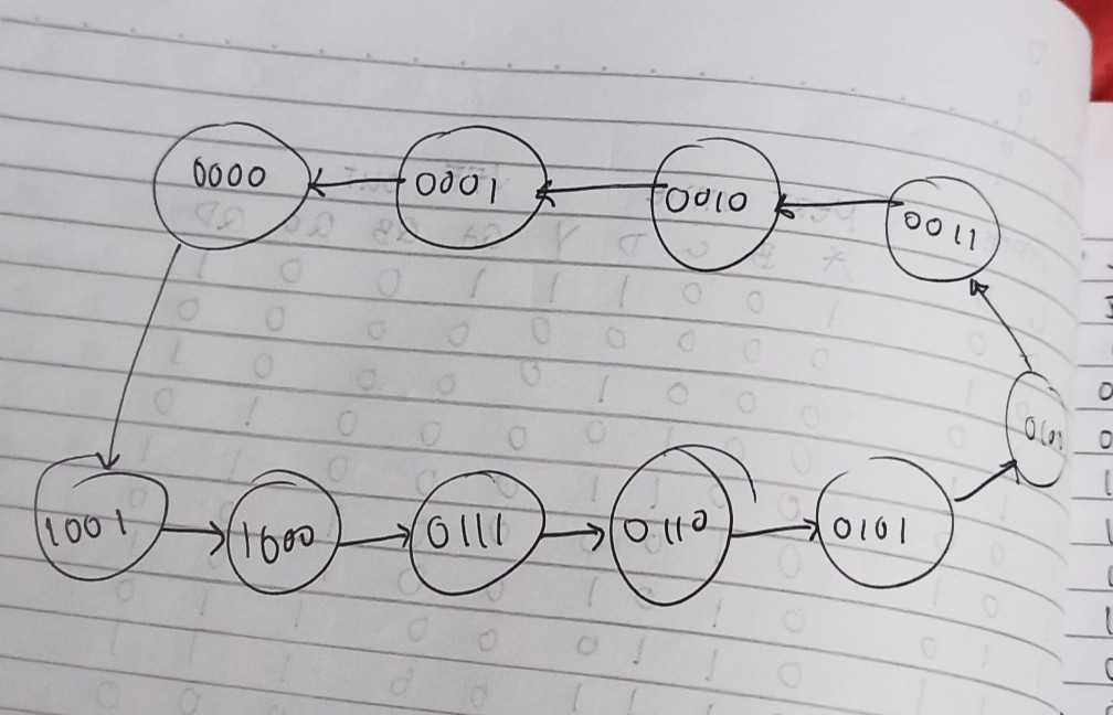
decade down-counter starting at 0
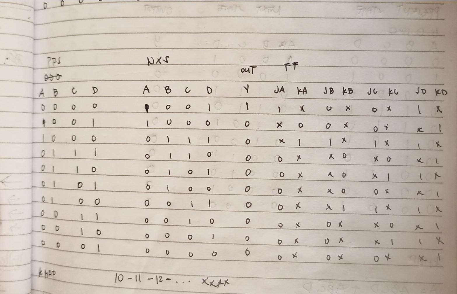
The table I see for this problem is:
$$\begin{array}{c|c}
\text{States} & \text{FF Inputs}\\\hline\\
{\begin{smallmatrix}\begin{array}{cccc}
Q_D & Q_C & Q_B & Q_A\\
\vphantom{\left.\overbrace{\begin{array}{ccc}J & K & T & D\end{array} } \right.}\\
0&0&0&0\\
1&0&0&1\\
1&0&0&0\\
0&1&1&1\\
0&1&1&0\\
0&1&0&1\\
0&1&0&0\\
0&0&1&1\\
0&0&1&0\\
0&0&0&1\\\\
1&0&1&0\\
1&0&1&1\\
1&1&0&0\\
1&1&0&1\\
1&1&1&0\\
1&1&1&1
\end{array}\end{smallmatrix}} &
{\begin{smallmatrix}\begin{array}{cccc}
Q_D & Q_C & Q_B & Q_A\\
\left.\overbrace{\begin{array}{cccc}J & K & T & D\\
1&x&1&1\\
x&0&0&1\\
x&1&1&0\\
0&x&0&0\\
0&x&0&0\\
0&x&0&0\\
0&x&0&0\\
0&x&0&0\\
0&x&0&0\\
0&x&0&0\\\\
x&x&x&x\\
x&x&x&x\\
x&x&x&x\\
x&x&x&x\\
x&x&x&x\\
x&x&x&x
\end{array} } \right. &
\left.\overbrace{\begin{array}{cccc}J & K & T & D\\
0&x&0&0\\
0&x&0&0\\
1&x&1&1\\
x&0&0&1\\
x&0&0&1\\
x&0&0&1\\
x&1&1&0\\
0&x&0&0\\
0&x&0&0\\
0&x&0&0\\\\
x&x&x&x\\
x&x&x&x\\
x&x&x&x\\
x&x&x&x\\
x&x&x&x\\
x&x&x&x
\end{array} } \right. &
\left.\overbrace{\begin{array}{cccc}J & K & T & D\\
0&x&0&0\\
0&x&0&0\\
1&x&1&1\\
x&0&0&1\\
x&1&1&0\\
0&x&0&0\\
1&x&1&1\\
x&0&0&1\\
x&1&1&0\\
0&x&0&0\\\\
x&x&x&x\\
x&x&x&x\\
x&x&x&x\\
x&x&x&x\\
x&x&x&x\\
x&x&x&x
\end{array} } \right. &
\left.\overbrace{\begin{array}{cccc}J & K & T & D\\
1&x&1&1\\
x&1&1&0\\
1&x&1&1\\
x&1&1&0\\
1&x&1&1\\
x&1&1&0\\
1&x&1&1\\
x&1&1&0\\
1&x&1&1\\
x&1&1&0\\\\
x&x&x&x\\
x&x&x&x\\
x&x&x&x\\
x&x&x&x\\
x&x&x&x\\
x&x&x&x
\end{array} } \right.
\end{array}\end{smallmatrix}}
\end{array}$$
The above is offered by way of comparison with your own thoughts.
I'm not going to draw out the k-maps. You can take the above table and generate those, if you like. And it's good practice. However, you can also readily plug any part of the above information into Steve Rickman's Logic Friday program (the latest version I have is 1.1.4.) It will minimize the logical algebra. If you do your own k-maps, verifying your findings using Logic Friday makes sense.
What I see in your question right now doesn't show your simulation efforts. So I can't be more help, yet. If you decide to include more in your question, I may then know better how to offer further details.
update
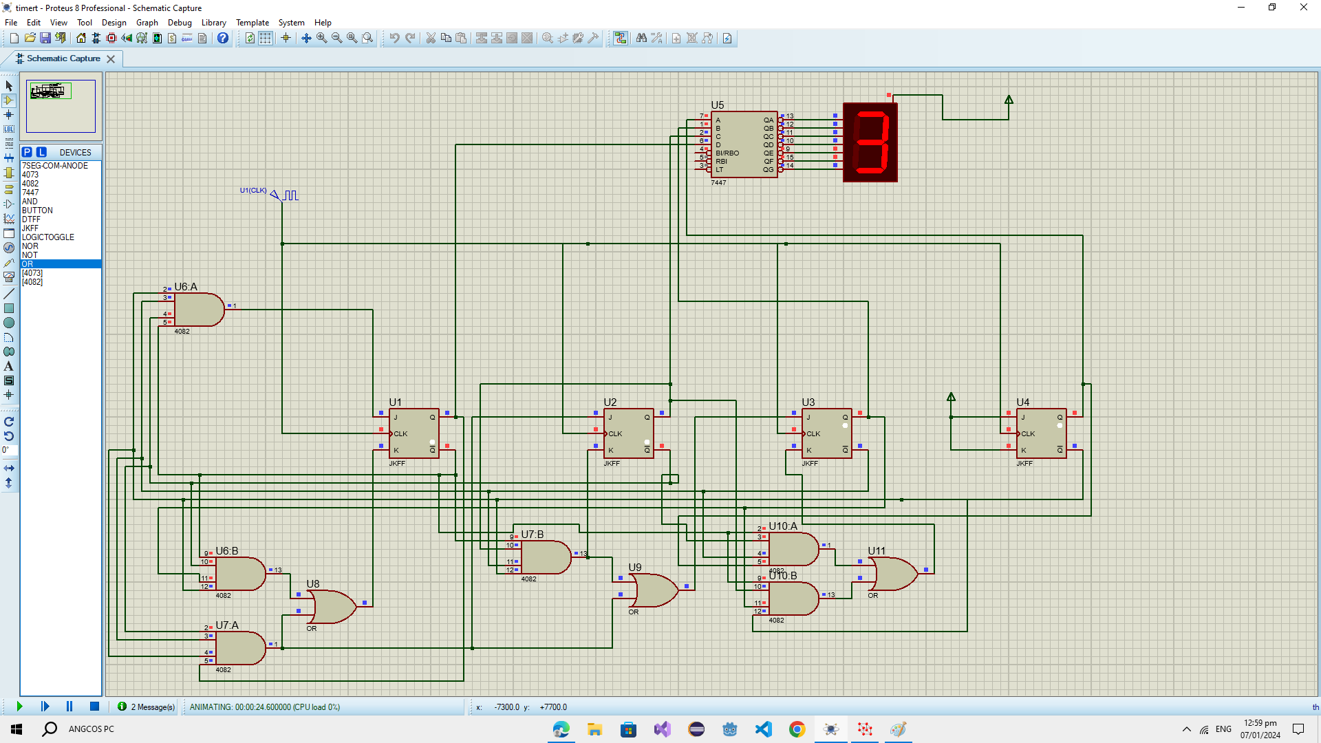
Now that you've added your work product, allow me to add mine for comparison, starting with the final result:
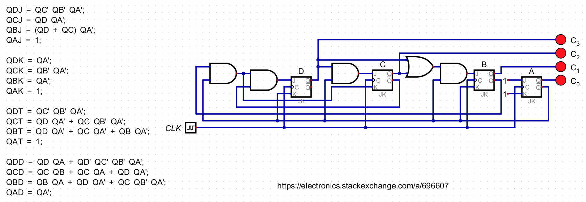
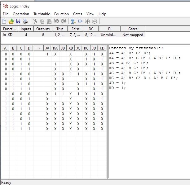
Then the Logic Friday table I prepared:
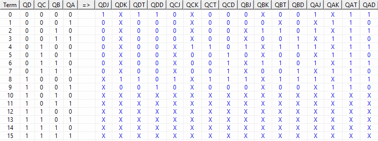
And finally the minimized output from Logic Friday:
Entered by truthtable:
QDJ = QD' QC' QB' QA';
QDK = QD QC' QB' QA';
QDT = QD' QC' QB' QA' + QD QC' QB' QA';
QDD = QD' QC' QB' QA' + QD QC' QB' QA;
QCJ = QD QC' QB' QA';
QCK = QD' QC QB' QA';
QCT = QD' QC QB' QA' + QD QC' QB' QA';
QCD = QD' QC QB' QA + QD' QC QB QA' + QD' QC QB QA + QD QC' QB' QA';
QBJ = QD' QC QB' QA' + QD QC' QB' QA';
QBK = QD' QC' QB QA' + QD' QC QB QA';
QBT = QD' QC' QB QA' + QD' QC QB' QA' + QD' QC QB QA' + QD QC' QB' QA';
QBD = QD' QC' QB QA + QD' QC QB' QA' + QD' QC QB QA + QD QC' QB' QA';
QAJ = 1;
QAK = 1;
QAT = 1;
QAD = QD' QC' QB' QA' + QD' QC' QB QA' + QD' QC QB' QA' + QD' QC QB QA' + QD QC' QB' QA';

Minimized:
QDJ = QC' QB' QA';
QDK = QA';
QDT = QC' QB' QA';
QDD = QD QA + QD' QC' QB' QA';
QCJ = QD QA';
QCK = QB' QA';
QCT = QD QA' + QC QB' QA';
QCD = QC QB  + QC QA + QD QA';
QBJ = QD QA' + QC QA';
QBK = QA';
QBT = QD QA' + QC QA' + QB QA';
QBD = QB QA + QD QA' + QC QB' QA';
QAJ = 1;
QAK = 1;
QAT = 1;
QAD = QA';
It looks to me as though you forgot to use Logic Friday's minimize option as shown below:

Sincerely, best wishes. It's good to see your activities!



minimizeoption that is available to you in Logic Friday. Hopefully, this helps. (I'll +1 your question with this additional added work product. Thanks!) \$\endgroup\$