2
\$\begingroup\$

I was pestering this community with questions for a while now. The answers I've received were put into the circuit below. I've decided to post it here in case someone else is looking for this kind of device (I've seen at least 3 related questions) and also as a sanity check for myself. enter image description here
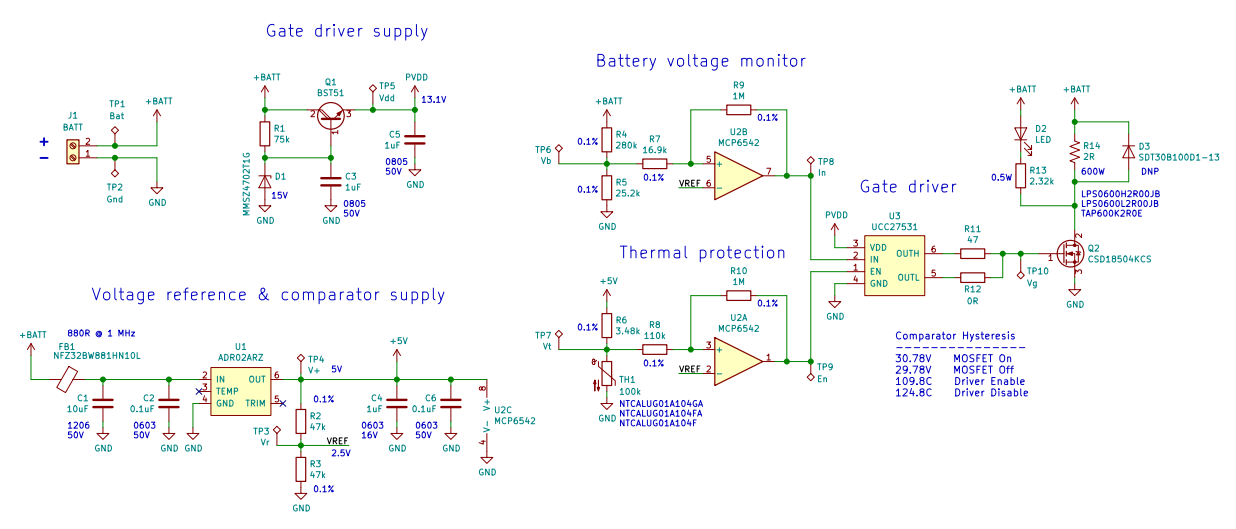
Here are the requirements:

  • max 2mA idle, operational down to 18.9V
  • standoff 29.8V, activate at 30.8V
  • dissipate 450W at least for 2 seconds.

The formal questions would be: Are there any glaring errors in the schematic above? Is there something I can do to improve it before sending to manufacturing?

My big thanks to everybody for their answers and patience.


UPDATE:

I also would like to mention that this circuit is a functional analog to one of the commercial devices we were successfully using before (and I believe to any basic shunt regulator as well). The differences are as follows:

  • They are using logic gate with schmitt trigger input as a comparator with hysteresis. I am using actual comparator chip for more precise and easily adjustable thresholds and hysteresis. I don't think this would make the circuit worse.
  • They are using zener + NPN regulator for everything: logic, reference and gate drive. I have split supply to have more stable reference and also higher voltage/current gate drive capability. I don't think this would make the circuit worse either.
  • They are driving the gate from the logic output via 100R resistor. I am using gate driver with split outputs to provide more "punch", especially for switching off the FET. The idea was to have an option to use IGBT and also reduce switching losses in MOSFET. This is one point that I am not sure about, because faster switching means the auto-oscillation frequency will also raise. Having said that, I can always increase gate resistor to get same slope as in commercial product.
\$\endgroup\$
8
  • \$\begingroup\$ Q1 will exceed its absolute maximum Veb rating when the battery is disconnected due to C3. Why the discrete regulator? \$\endgroup\$ Commented Jan 10 at 20:36
  • \$\begingroup\$ @JonathanS. Won't integrated resistor in BST51 deal with this? I actually had an answer here suggesting a diode. If built-in resistor is no help I'll add the diode. Did not understand the question about regulator. Discrete as opposed to what? \$\endgroup\$
    – Maple
    Commented Jan 10 at 21:38
  • \$\begingroup\$ No, the integrated resistor doesn't protect anything. Why don't you just use an integrated regulator like the LM317 or MAX17651? Also, are you sure that you won't get more than 1V of drop along the wires when your circuit suddenly starts pulling 15A from the battery? (Considering inductance as well.) It'll likely oscillate... \$\endgroup\$ Commented Jan 10 at 22:20
  • \$\begingroup\$ @JonathanS. OK, I'll add a diode. I could not find LDO with sub-mA quiescent and up to 2.5A output. There are few for 1A but they are 10x more expensive than discrete solution. No, I am not sure. But that is where comparator should kick in and switch off the FET. It will most definitely oscillate. Expensive commercial devices actually generate PWM themselves. Cheaper rely on hysteresis, for essentially the same result. \$\endgroup\$
    – Maple
    Commented Jan 10 at 22:33
  • \$\begingroup\$ Why would you need 2.5A? I can only see a gate driver connected to PVDD, which barely needs any steady-state current. The switching current spike comes from C5 anyway. Also, if this thing oscillates at more than a few kHz, your FET will likely blow up due to switching losses. 15A at 30V is no joke. Other devices attached to the battery might also be damaged by the oscillation. \$\endgroup\$ Commented Jan 10 at 23:51

0

Your Answer

By clicking “Post Your Answer”, you agree to our terms of service and acknowledge you have read our privacy policy.

Browse other questions tagged or ask your own question.