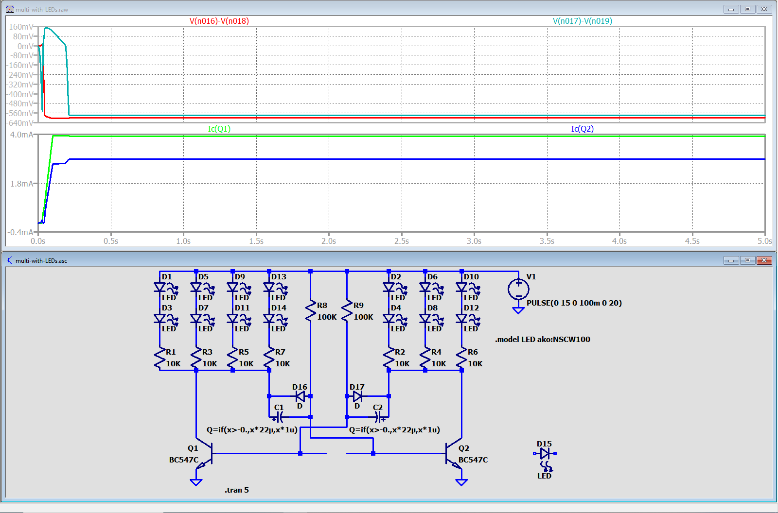
With some tinkering with a bespoken polarized-cap model parameters I've managed to reproduce the behavior the OP described for their circuit. In this simulation, reverse-voltage current leakage is modeled with standard default diodes D16 and D17 from LTspice's standard.dio, without any adjustment made to saturation current or other diode model parameters. The current leakage should be included in the model: the circuit with non-polarized capacitors C1, C2 would oscillate unconditionally, no "extra LED" is required to be added in the transistor base networks.
Now, adding reverse-voltage current alone into the model is not sufficient to suppress oscillations. The oscillations can be suppressed with the coarse ideal-diode model of leakage current; however, with voltage polarity reversed, the real valve effect turns off not abruptly, as if with ideal diode switch-on, but softly, as if with real diodes. Now, in the real electrolytic capacitor, the transition to reverse polarity is also accompanied with capacitance value variation. I have no idea of how much this capacitance value changes; this parameter is not readily available in datasheets. If we adopt the rather drastic plummeting to a value of 1 uF at reverse voltages, as in the formula for capacitance values for C1,C2 capacitors of my simulation, Q = if(x>-0., x*22µ, x*1u), the simulation plot shows that oscillations do not start and diodes in both multivibrator legs light up constantly (Ic(Q1)=4mA, Ic(Q2)=2.9mA):

The upper plot pane shows reverse polarity voltages of -0.56V across capacitors C1,C2.
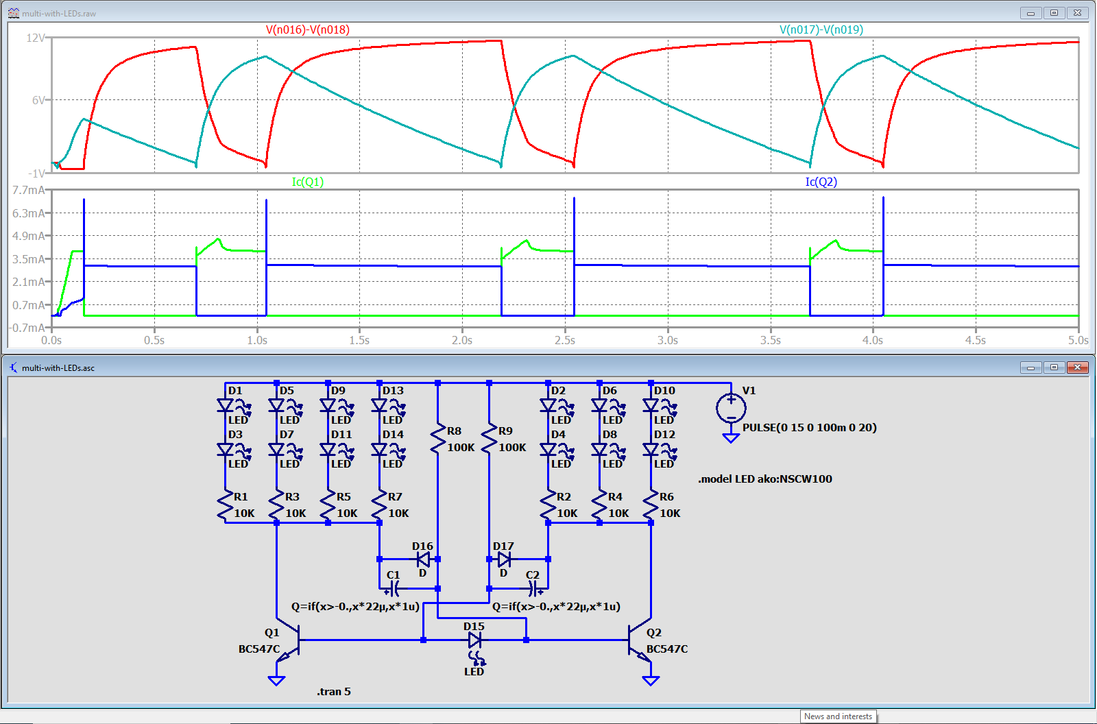
With the "extra LED" D15 added, the oscillations start:

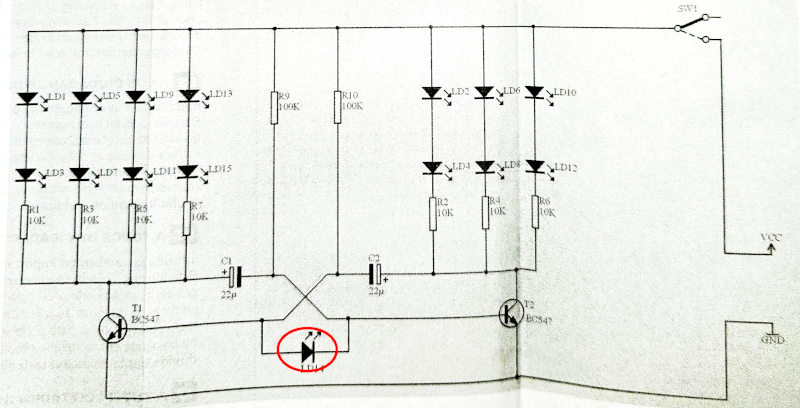
the "extra LED" is blinking exactly like it is described in the OP post:

Disclaimer: The assumptions about the electrolytic capacitor model and model parameter values in this post are rather arbitrary. I am introducing the model and posting the simulation plots here with the only purpose to indicate the possible explanation of the OP's observations. No sources I've consulted support the validity of this model for simulating electrolytic capacitors in circuits with SPICE simulators.


