2
\$\begingroup\$

I tend to struggle computing the Thévenin voltage. Here is a simple example in which I reason wrongly. After open-circuiting, we reach the following:
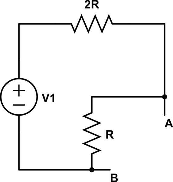
schematic

simulate this circuit – Schematic created using CircuitLab

Here I would argue as follows:

  • As \$V_{\text{Th}}\$ is the voltage difference from \$B\$ to \$A\$, I place \$V_{\text{Th}}\$ next to \$A\$ and ground next to \$B\$:
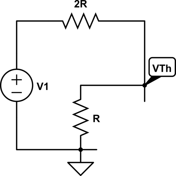
schematic

simulate this circuit

  • Now the voltage across \$2R\$ is \$V_{\text{Th}}-V_1\$, giving \$V_{\text{Th}} = V_1 + 2IR\$.

The solution, consisting of the following:

enter image description here

does point to my reasoning being wrong.


What is wrong with my reasoning? How is the reasoning of the solution explained?

\$\endgroup\$
4
  • \$\begingroup\$ Shouldn't this be an excellent chance to apply graph theory to your question? (Given your interest in the topic.) \$\endgroup\$ Commented Jan 12 at 14:47
  • \$\begingroup\$ Just: A=Matrix([[1,-1,0],[-1,0,1]]) and C=Matrix([[1/(2*r),0],[0,1/r]]) and W=A.T*C*A and P=W.extract([0],[0]) and Q=W.extract([1,2],[0]) and R=W.extract([1,2],[1,2]) and then find that -P.inv()*Q.T*Matrix([v1,0]) gives Matrix([[v1/3]])? (Currents in and out of the voltage nodes would be from the Schur complement: (R-Q*P.inv()*Q.T)*Matrix([v1,0]) equals Matrix([[ v1/(3*r)],[-v1/(3*r)]]).) \$\endgroup\$ Commented Jan 12 at 14:53
  • \$\begingroup\$ Sam, if we are done here, please take note of this: What should I do when someone answers my question. If you are still confused about something then leave a comment to request further clarification. \$\endgroup\$
    – Andy aka
    Commented Jan 13 at 9:51
  • \$\begingroup\$ Sam, also consider this. In any case, pressures from others aside, you have the complete right to decide on your own what answers or doesn't answer your question. Regardless of what fits your bill, best wishes. \$\endgroup\$ Commented Jan 13 at 15:43

3 Answers 3

4
\$\begingroup\$

What is wrong about my reasoning? How is the reasoning of the solution explained?

You need to resolve current i.e. you need to establish what \$I\$ is.

\$I\$ equals the supply voltage (\$V_1\$) divided by the resistance of the two resistors in series: -

$$I\hspace{1cm} =\hspace{1cm} \dfrac{V_1}{2R + R}\hspace{1cm}= \hspace{1cm}\dfrac{V_1}{3R}$$

I'm sure if you substitute this you will get the right formula.

Actually, looking at your first formula you have got things back to front: -

$$V_1 = 2IR + V_{TH}\hspace{1cm}\text{or}\hspace{1cm} V_{TH} = V_1 - 2IR$$

Drilling down we get: -

$$V_{TH} = V_1 - 2R\cdot\dfrac{V_1}{3R}$$

And, \$V_{TH}= \dfrac{V_1}{3}\$

\$\endgroup\$
1
\$\begingroup\$

Start with this:

"Now the voltage across 2R is VTh−V1, giving VTh=V1+2IR."

Nope. It's V1 - VTh.

\$\endgroup\$
0
\$\begingroup\$

The problem with your reasoning is that: you are not taking care about the polarity of voltages.

You should always define the polarity of the voltage variable you assign (Where do you assume the high "\$+\$" node and low "\$-\$" node?). This is like assuming the current direction when we deal with unknown current.

In this circuit, after opening the AB terminal, it is clear that the current is flowing clockwise.

So, the polarity of voltages on the resistors are counterclockwise (I am using voltage rise).

This means that the voltage across 2R is (\$V_1-V_{TH}\$) NOT (\$V_{TH}-V_1\$).

\$\endgroup\$

Your Answer

By clicking “Post Your Answer”, you agree to our terms of service and acknowledge you have read our privacy policy.

Not the answer you're looking for? Browse other questions tagged or ask your own question.