2
\$\begingroup\$

I wanted to design a small temperature-regulated DC heater for the sake of educational purposes in the field of control theory.

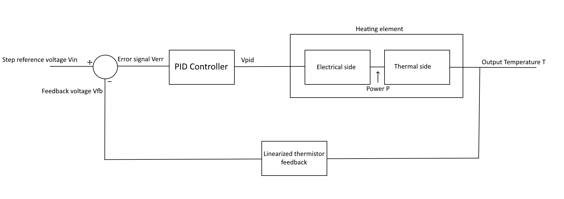
The idea is to heat up a resistive element through a buck converter of some sorts and to regulate that with a control loop involving a PID controller for the controller and a linearized thermistor for the feedback, like pictured in the following block diagram:

enter image description here

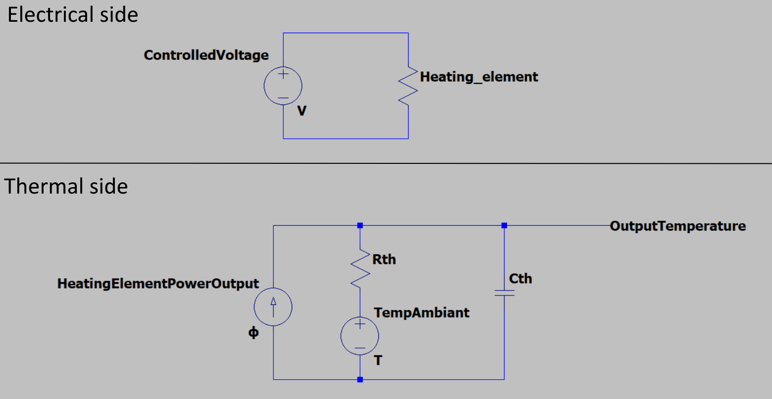
I naturally wanted to first analytically find the transfer function of that heating system which incorporates both electrical and thermal equations, the schematic of the system I came up with looks like the following:

enter image description here

Please note that for the sake of simplicity:

  1. I am oversimplifying the electrical side, "ControlledVoltage" should eventually be driven by a buck converter but as this isn't related to my current issue I'll assume that it is directly proportional to the output voltage of the PID controller ("Vpid").
  2. For the thermal side I'm using the thermal-electrical analogy to model the thermal behavior of the heating system through an electrical circuit

So, it should be easy to find the transfer function of the thermal side as it's nothing more than an equivalent RC circuit with the thermal flux ϕ as an input and the temperature of the heating system as an output.

However, when attempting to find the transfer function of the electrical side with the controlled voltage as an input and the dissipated power in the resistor as an output, I obviously find:

$$P = \frac{V^2}{R}$$

Which is a non-linear equation, which is also a huge problem since transfer functions are by definition linear time-invariant systems, meaning that I cannot use this equation to model my transfer function or that I need to find some way around it.

So my question might appear obvious now, how can I find the transfer function of my system? I am obviously not the first person in the world to attempt to design a regulated DC heater and as such probably also not the first one to stumble across this issue, is there some tricks to linearize the system, some equations I missed, something I simply didn't understand about transfer functions, or maybe an entirely different design philosophy I missed?

Please note that I am aware that I could build the system, find the impulse response experimentally, curve-fit it and eventually find the transfer function. But again, I'm doing this little project for educational purposes and I would greatly appreciate finding the transfer function analytically.

Any help would be greatly appreciated.

\$\endgroup\$
2
  • \$\begingroup\$ "Step reference voltage in" should be called "Set Temperature". Have a look to this electricalengineeringinfo.com/2017/05/… \$\endgroup\$
    – Antonio51
    Commented Jan 19 at 9:54
  • 1
    \$\begingroup\$ Just use PWM on your resistor, that will get rid of the V squared. It's also more efficient and simpler. \$\endgroup\$
    – bobflux
    Commented Jan 19 at 11:36

1 Answer 1

4
\$\begingroup\$

There are several ways to handle the non-linearity implied by the power being proportional to V2.

  • Linearise around an operating point. For small disturbances, power will be roughly proportional to voltage. However, this solves the problem only in the region of that particular point. This is a well used approach, often used to get a gm figure for bipolar transistors at a particular bias point. However, you still need to make sure the system is stable at all heating levels, you will be powering on with the system cold, see the next point.
  • Make the system stable at a range of gains. If you want the system to operate with the different gains you get from operating at high or low voltage, then you need to be very generous with your gain and phase margins, and tolerant of slower than ideal settling times over a range of settings. This can be very easy to do if you use Bode plots for design, you simply move the low-pass elements up, and the high-pass ones down in frequency, to give you an extended 6dB slope region in the middle. Aim for over-damping. With a heating system, depending on the tolerance of your load to an over-heat (for instance biological samples or soft plastics), you must have no possibility of an overshoot.
  • As you have a heater, lose the buck converter, use simpler PWM, and now you have a linear transfer function between PWM setting and heater output power (power = full_power * PWM_fraction). Take advantage of the fact that a heater time constant will be seconds to 10s of seconds, so the PWM can be very slow. My oven controller uses a 20 seconds PWM period. I had a precision lab hotplate that managed quite happily with a two seconds period.
\$\endgroup\$
3
  • \$\begingroup\$ Lots of really good points in this answer, thanks a lot! My first idea was actually to use a PWM without any filtering (unlike buck converters), but I calculated the transfer function in my head and reached the wrong conclusion that it was going to be non-linear. Which made me switch to what I believed would've been simpler to work with (ie: a stable voltage at the output of a buck converter). Your last point actually puzzled me and made me do the calculation on paper which got me the correct, linear, result. \$\endgroup\$
    – tampler
    Commented Jan 19 at 12:59
  • \$\begingroup\$ @tampler If you're doing Peltier cooling, you must not use PWM, only a steady voltage, as they get very inefficient with bursty supplies. Resistive heaters OTOH retain 100% efficiency however you drive them. AFAIK, all commercial applications of controlled resistive heating use PWM rather than steady voltage control, because you can. \$\endgroup\$
    – Neil_UK
    Commented Jan 19 at 13:30
  • \$\begingroup\$ I'd agree PWM is the way to go, but as an addition, I think it would be possible to linearize "entirely" by transforming the output of the PID by taking the root, and using that to control V. An analog square root is maybe a heavy on components, but if your PID is being done on say, a microcontroller, then you can do it easily. \$\endgroup\$
    – mbrig
    Commented Jan 19 at 21:06

Your Answer

By clicking “Post Your Answer”, you agree to our terms of service and acknowledge you have read our privacy policy.

Not the answer you're looking for? Browse other questions tagged or ask your own question.