1
\$\begingroup\$

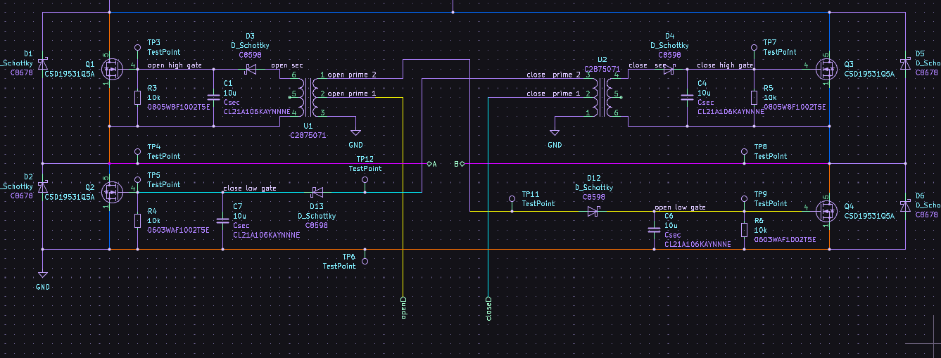
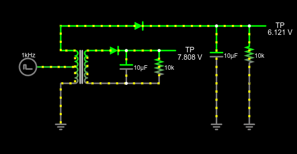
I am trying to drive both a high-side and a low-side MOSFET as part of an H-Bridge circuit and had the idea to gang both MOSFETs with the same input. My idea was if I drive one side of a center-tapped transformer the other side being magnetically coupled to the first half of the primary would act like a step-up transformer and the other side would be in phase and have a magnitude of 2x the input single.

simulation

the signal represents a pulsed DC square wave generated by a digital pin of a microcontroller. Are center-tapped transformers supposed to work like this? Is this a valid method to drive a MOSFET H-Bridge? am I risking sending too much voltage into the gate pins? is this even a good idea?

enter image description here

\$\endgroup\$
5
  • \$\begingroup\$ It behaves like a coupled inductor where the signal directions are cancelling the magnetic flux in the core. \$\endgroup\$
    – DKNguyen
    Commented Jan 20 at 1:27
  • \$\begingroup\$ Why not just a single gate drive transformer with four secondary windings that drives all four MOSFETs at once? That would bring it down to a single MCU pin (plus something to drive the transformer). \$\endgroup\$ Commented Jan 20 at 1:28
  • 1
    \$\begingroup\$ Why not a bootstrap driver? ICs are cheaper than transformers these days. \$\endgroup\$ Commented Jan 20 at 1:39
  • \$\begingroup\$ Simulation results would tell you whether it would look OK. However, why you would want one MOSFET drive to have twice the magnitude of the other is beyond me. Maybe you are using a step up transformer. Details are needed. \$\endgroup\$
    – Andy aka
    Commented Jan 20 at 9:55
  • \$\begingroup\$ @Andyaka the turns ratio is N1:N2:N3:N4 1:1:1.11:1.11 part number: VPT85BB-01A datasheet.lcsc.com/lcsc/… \$\endgroup\$ Commented Jan 20 at 17:26

1 Answer 1

1
\$\begingroup\$

Center tapped transformers (or any transformers (or any components)) don't care about single pins. What matters is the voltage across each coil (which has two pins) and the current through each coil. A center-tapped coil is the same as two coils connected together in the middle.

The way you're using the center-tapped coil makes an autotransformer configuration. It saves wire compared to a two-coil transformer, but doesn't provide isolation. Image from Wikipedia:

autotransformer schematic

It works just how you'd expect a transformer to work - the voltage ratio is the turns ratio. At least, it does for sine-wave AC. Passing a square wave through a transformer distorts the wave, but you probably already know that and don't care.

You're using the transformer for two transformations at once - the left side as an autotransformer and the right side as a normal transformer. If this works for you, then great. You found a trick to do something with less parts. Congratulations.

\$\endgroup\$

Your Answer

By clicking “Post Your Answer”, you agree to our terms of service and acknowledge you have read our privacy policy.

Not the answer you're looking for? Browse other questions tagged or ask your own question.