0
\$\begingroup\$

I would like to trigger a 3 V line (a push dimmer circuit) with a touch button (which is powered by 12 V).

Closing the 3 V will turn off (short press)/turn on (short press)/dim (long press) the LED strip.

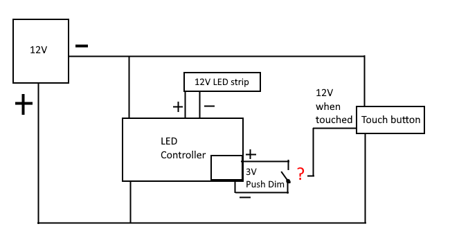
Here is my complete circuit:

enter image description here

How can I connect the outgoing 12 V line from the touch button to close the 3 V line (the red question mark)?

Can this be realized by a transistor, optocoupler, etc.?

Hardware used:
LED controller: GLEDOPTO GL-C-013P (zigbee (3 wire/2 wire 2in1)) LED Conttroller
Touch button: Touch Button

\$\endgroup\$
2
  • 2
    \$\begingroup\$ Please edit your question to add links to datasheets for the items "LED Controller" and "Touch button". Then we can see their specifications, so we'll be able to give you useful answers. \$\endgroup\$ Commented Jan 22 at 18:15
  • \$\begingroup\$ I have addded links to the hardware I am using. There are no specs though. \$\endgroup\$
    – ZTHawk
    Commented Jan 23 at 7:16

2 Answers 2

1
\$\begingroup\$

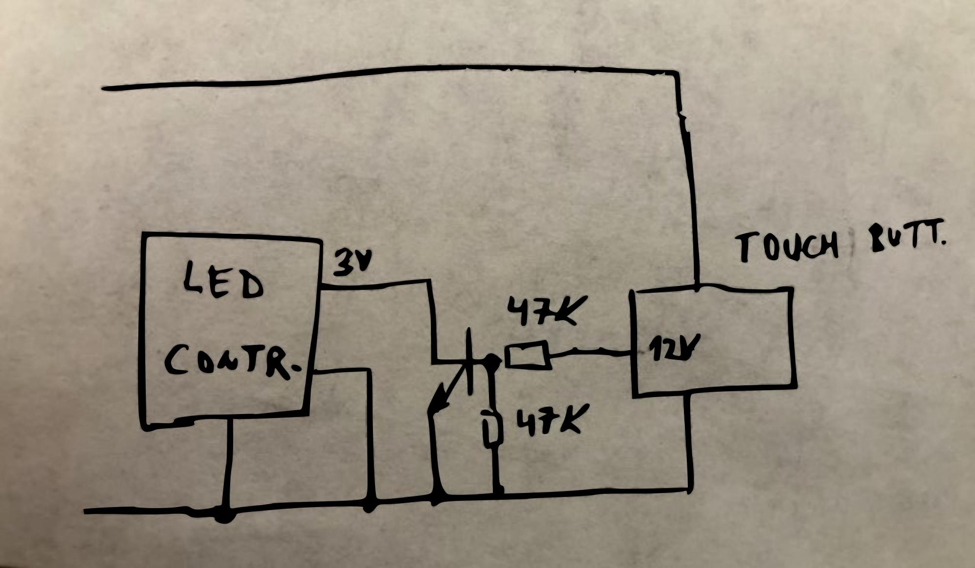
If the gnds of 3V and 12V are or can be connected together (not isolated), you can use a NPN transistor like 3904 with 47k in base. Otherwise you have to use an optocoupler.

enter image description here

\$\endgroup\$
3
  • \$\begingroup\$ I do not know if they are connected to the same GND or if the LED controller is isolating them. \$\endgroup\$
    – ZTHawk
    Commented Jan 23 at 7:29
  • \$\begingroup\$ Just measure the resistance with multimeter between Gnd and minus of push input. \$\endgroup\$ Commented Jan 23 at 13:13
  • \$\begingroup\$ I have used a BC547C as NPN transistor. This is working. Thank you \$\endgroup\$
    – ZTHawk
    Commented Feb 1 at 18:57
0
\$\begingroup\$

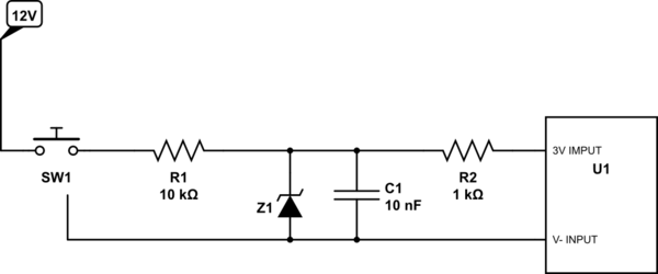
Reduce the voltage with a Zener diode. Put a 10 kΩ resistor in series with the Zener diode to limit the current to the Zener. The capacitor and the second resistor will debounce the signal, avoiding erratic signals from the switch when pressing and releasing.

schematic

simulate this circuit – Schematic created using CircuitLab

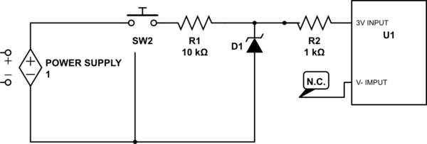
If you are using a power supply with screw terminals (not plug in like on the Ali Express website), you can do the following: Use the ground of the power supply and leave the V- not connected. Both schematics show a touch sensor switch (with the additional ground line).

ATTENTION: Do not use the "C" connections as ground.

schematic

simulate this circuit

\$\endgroup\$
8
  • \$\begingroup\$ I do not quite understand how to connect this. I assume the 12V is the line comming from the touch button. But what about the two 3V lines (+ and -). Is the GND the main one (from 12V) or from the LED controllers 3V? \$\endgroup\$
    – ZTHawk
    Commented Jan 23 at 7:33
  • \$\begingroup\$ The 3V and 12V GND should be the same in this example. \$\endgroup\$
    – S_G
    Commented Jan 23 at 8:25
  • \$\begingroup\$ Normally the LED controller ground and the 12V supply ground should be the same. You can check it by measuring the impedance between the two grounds with a multi meter. If it's not, you will have to connect them together. But that would be very strange that they were not the same. \$\endgroup\$
    – Fredled
    Commented Jan 23 at 9:20
  • \$\begingroup\$ If you are using an inductive touch sensor, you don't need the capacitor (C1) and R2 neither but it's not bad to keep it. \$\endgroup\$
    – Fredled
    Commented Jan 23 at 9:28
  • \$\begingroup\$ I have just realized that I am not understanding GND. My LED driver (230V in / 12V out) has just a 12V + and - output connector. Is the minus 12V equal to GND? If not, where is my GND? \$\endgroup\$
    – ZTHawk
    Commented Jan 23 at 20:13

Your Answer

By clicking “Post Your Answer”, you agree to our terms of service and acknowledge you have read our privacy policy.

Not the answer you're looking for? Browse other questions tagged or ask your own question.