1
\$\begingroup\$

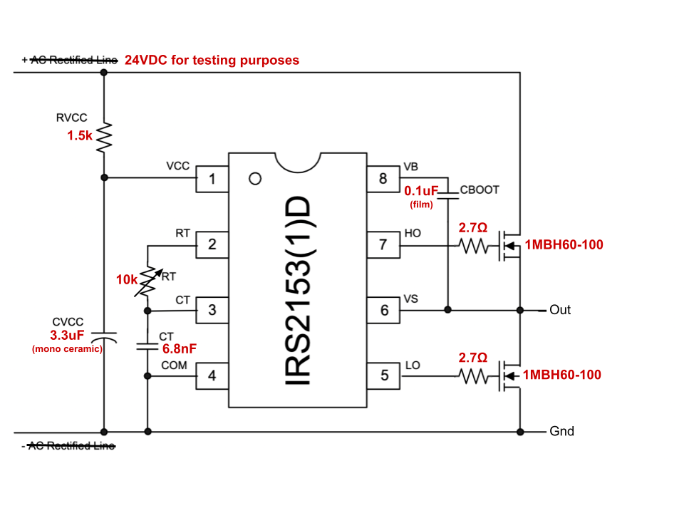
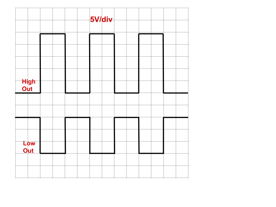
Using an IRS2513 half bridge driver tuned at 30 kHz with 1MBH60-100 1000 V, 60 A IGBTs, the driver is giving the high-side gate the full 24 V input voltage.

I have included a picture of how I configured the driver and how the oscilloscope looked when measuring (measured from HO to GND and LO to GND).

Why is this happening? The driver has an internal 15.4 V zener clamp.

IRS2513

scope

\$\endgroup\$
3
  • 2
    \$\begingroup\$ Do you measure the high-side gate drive output with respect to the ground or with respect to the high-side switch's source pin? Also, is there any load? \$\endgroup\$ Commented Jan 22 at 20:28
  • \$\begingroup\$ So are you asking about how a high-side bootstrap circuit works? electronics.stackexchange.com/questions/624470/… \$\endgroup\$
    – G36
    Commented Jan 22 at 20:32
  • \$\begingroup\$ @RohatKılıç I can't believe I missed that... Switching the HO probe's ground to VS, I am now measuring the correct voltage. Thank you! \$\endgroup\$ Commented Jan 22 at 20:47

1 Answer 1

1
\$\begingroup\$

Turns out my scope probes were placed incorrectly. I was measuring from HO to Gnd and should have been measuring from HO to VS.

\$\endgroup\$
3
  • \$\begingroup\$ Make sure you didn't probe anything else whilst the gnd clip was connected to the VS. \$\endgroup\$ Commented Jan 22 at 20:50
  • \$\begingroup\$ Also don't forget to accept your own answer (as, apparently, your problem is solved) so that the question doesn't remain open. \$\endgroup\$ Commented Jan 22 at 20:51
  • \$\begingroup\$ Sure thing! However I cannot accept my own answer until two days have passed. \$\endgroup\$ Commented Jan 22 at 20:56

Your Answer

By clicking “Post Your Answer”, you agree to our terms of service and acknowledge you have read our privacy policy.

Not the answer you're looking for? Browse other questions tagged or ask your own question.