4
\$\begingroup\$

I have created a footprint for NetTie of custom size (I wanted 0.2mm pad/connection), as the library-provided one has the size of 0.5mm and is too big.

I have tried two ways of routing:

  • from other pad to NetTie: trying to route it from outside (of NetTie) the track stops before reaching NetTie's pad

Routing from right-to-left

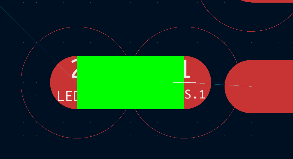
  • when trying to start the track from NetTie, when clicking pad of NetTie, this green block shows up, the screen blinks and no track appears.

routing from NetTie

Most probably there is a DRC rule on the way. To prevent it, I ensured that during footprint creation all layers, polygons etc. were the same as the working NetTie from library. Unless there are some additional settings invisible in KiCAD of which I don't know.

What to check to make this custom made NetTie to be possible to route?

\$\endgroup\$

2 Answers 2

7
\$\begingroup\$

Note: the below applies to KiCad 7.0.0 and later.

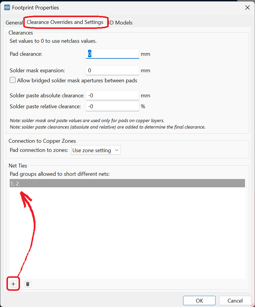
Your footprint needs to have net tie properties set, in footprint properties > clearance overrides > pad groups allowed to short different nets.

The purpose of this is perhaps self-explanatory, but for completeness' sake, this field tells the DRC (and also the router) that these two (or more) pads are part of a net tie between two different nets, and that it should ignore any copper clearance violations between these nets.


The below applies to KiCad versions prior to 7.0.0:

You need to add the "net tie" tag to the footprint. (It might be "net_tie"? I forget.) As I recall, this has to be the first tag, but you can put any other tags you like after it.

The presence of this tag tells the DRC and router that the footprint is a net tie, and causes them both to ignore all DRC clearance violations for this footprint. It doesn't matter if there are additional non-net-tie pads; all clearance violations are completely ignored. (Maybe all DRC violations in general? I haven't used old versions in a while.)

\$\endgroup\$
4
\$\begingroup\$

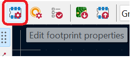
@Hearth It worked, thanks! To make it clear: Footprint needs to be opened in Footprint Editor, next click on Edit Footprint properties (yes, there are more than one 'Properties')

FtptProperties

Next, go to the 'Clearance Overrides and Settings', click small '+' and place desired pads (in my case: 1, 2)

enter image description here

\$\endgroup\$

Your Answer

By clicking “Post Your Answer”, you agree to our terms of service and acknowledge you have read our privacy policy.

Not the answer you're looking for? Browse other questions tagged or ask your own question.