0
\$\begingroup\$

Background: I have a handheld Wonderswan with an IPS display and flash cart. These mods mean that it uses more power than the original. The handheld uses a 1.5v AA battery, so I've been working on an extra mod that allows a 3.7v lithium battery with an LDO (to drop to 1.5v) to give it a longer life. This part works. I'm also a beginner with electronics design.

The part that I'm trying to solve is that the LDO has a max draw of around 700mAh and when the handheld boots with a flash cart, the display can't get the amps it needs to turn on. Additional note is that there's a soft power button (ie. there's no physically connecting switch).

Here's where I'm getting stuck.

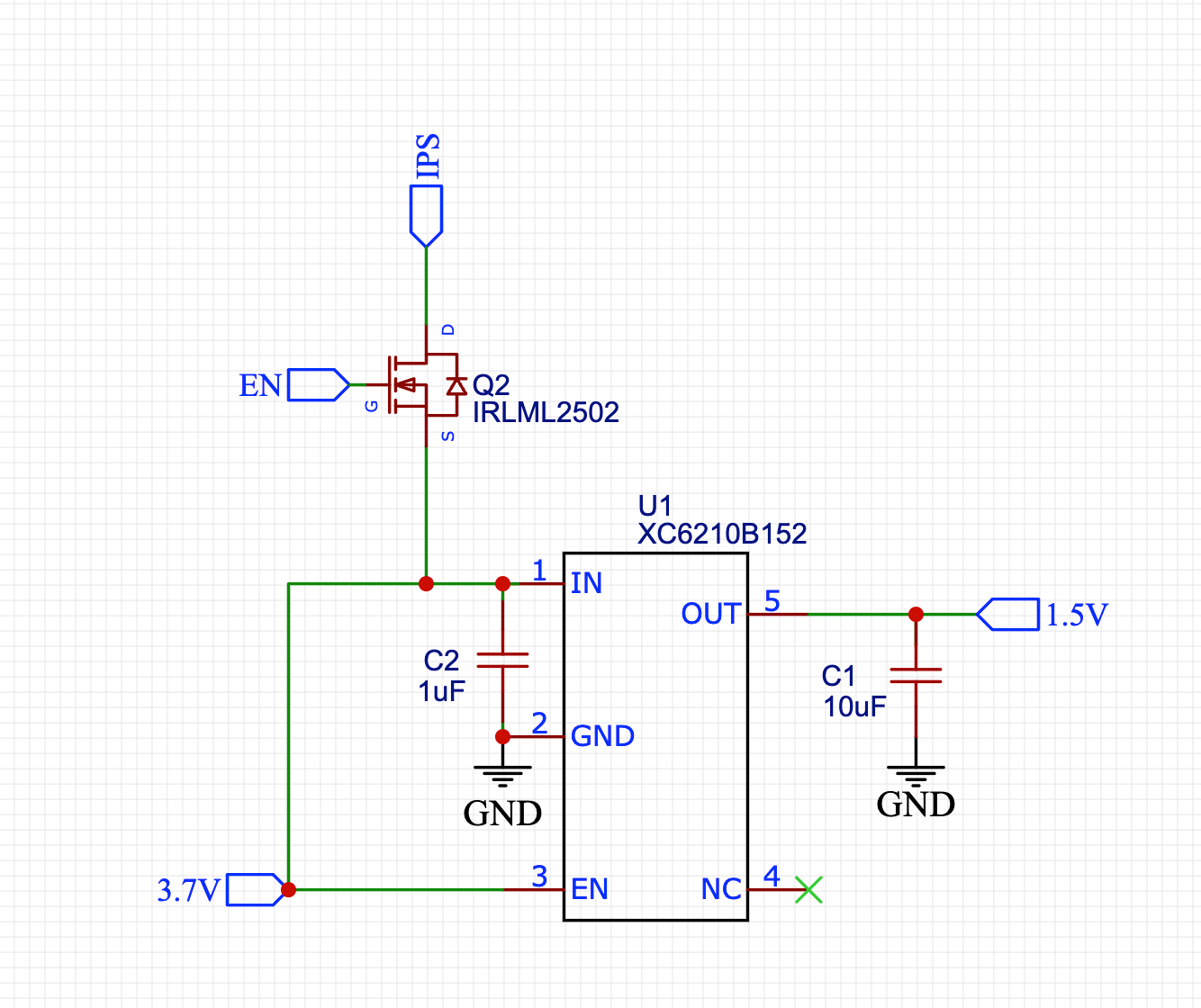
I've added a MOSFET (IRLML2502PBF) connected as such:

  • Source connected to 3.7v battery
  • Gate connected to 1.5v rail that is only powered when the handheld is turned on (otherwise it's 0v, not ground)
  • Drain connected to IPS display

This is the schematic (where EN is the 1.5v rail):

Schematic of mosfet

This design ends up with the MOSFET never putting any positive (or useful) voltage out on the drain (so the display remains off).

I'm sure it's my lack of knowledge that's got this wrong. Can anyone advise (gently!) how to fix this?

A side note: I originally designed this with a 2N2222 transistor, and it did (mostly) work, but I found that sometimes the display wouldn't come on, and my guess was that either the transistor wasn't switching fast enough, or it was limiting the voltage (whereas this MOSFET, I thought wasn't supposed to have much/if any voltage drop).

\$\endgroup\$
4
  • \$\begingroup\$ For n channel mosfet Gate voltage should be greater than source voltage and Vgs should be greater than Vt. \$\endgroup\$
    – Varun
    Commented Jan 31 at 12:03
  • \$\begingroup\$ Use a P channel device with the source connected to 3.7V and drain to IPS. Add a resistor from source to gate and pull the gate down to enable it. You may need to use parametric tables as you will need a device characterised for 2.5V operation. Be sure to check the drain current rating. \$\endgroup\$ Commented Jan 31 at 13:06
  • \$\begingroup\$ An alternative to my previous comment is an outboard boost circuit. \$\endgroup\$ Commented Jan 31 at 13:13
  • 1
    \$\begingroup\$ Not an answer to your question, but if you used a buck regulator instead of the LDO you'd double the battery lifetime. You're throwing away about 60% of your battery's capacity as heat in the LDO. \$\endgroup\$
    – brhans
    Commented Jan 31 at 13:50

2 Answers 2

2
\$\begingroup\$

Your FET is an N-channel device, and so it requires Vg to be higher than Vs to turn on. And that never happens, if Vs is 3.6V and Vg is 1.5V so Vgs is always negative and FET is always off.

I also don't see how it could have worked with a 2N2222 transistor either.

The FET also has an intrinsic diode as drawn, so basically the IPS node on drain will always get about 0.7V less than source voltage.

So first of all you need a P-channel FET, with Source to 3.6V and Drain to IPS. But then you need to pull the gate down to 0V to turn it on, and leave at 3.6V to turn off. You need a transistor to take in the 1.5V signal and invert it and level shift to 0V/3.6V signal.

Or you could buy a load switch that has an active high enable input and has a logic level threshold so that 1.5V can be used as the enable.

\$\endgroup\$
0
\$\begingroup\$

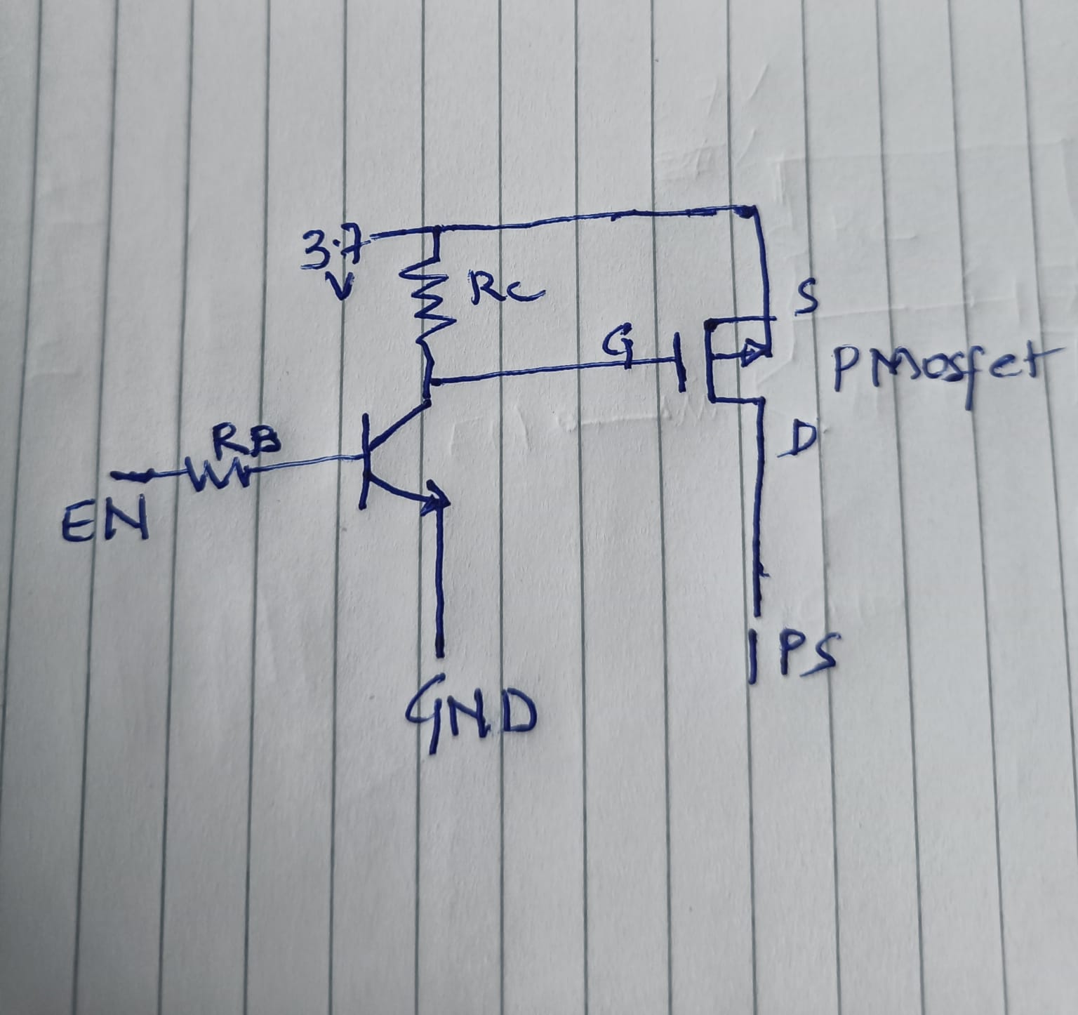
circuit DiagramCircuit like above should work for this

\$\endgroup\$

Your Answer

By clicking “Post Your Answer”, you agree to our terms of service and acknowledge you have read our privacy policy.

Not the answer you're looking for? Browse other questions tagged or ask your own question.