0
\$\begingroup\$

I'm experimenting with making a simple intercom from two old corded telephones.

I'm including a buzzer and momentary switch on each end for an incoming call alert.

Below is the circuit I made using two duplex RJ-11 phone jack boxes. This is working.

Inside the jack on the left side of the circuit:

  • The red wire is cut and then one end is connected to the "G" wire coming outside of the jack and the other end is connected to the "R" wire coming outside of the jack.
  • The green wire inside this jack is left intact inside the jack and only the two red ends and the yellow and black wires are used outside the jack.

Inside the jack on the right side of the circuit:

  • The red wire inside the jack is left intact inside the jack
  • Only the green, yellow and black wires are used outside this jack.

My question is: how are the two red wire ends and the green wires inside the two jacks connecting in this circuit?

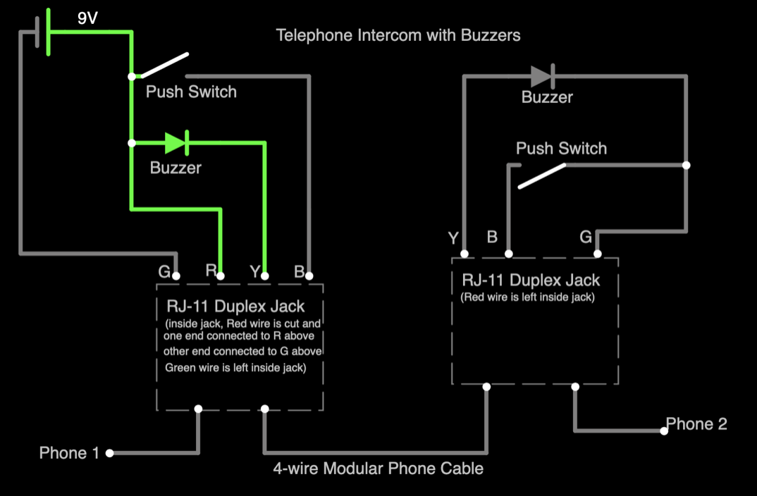
enter image description here

\$\endgroup\$
4
  • \$\begingroup\$ What do you want to use them for? Connecting two phones in local-battery mode typically requires two wires only. \$\endgroup\$
    – PMF
    Commented Feb 1 at 15:47
  • \$\begingroup\$ I'm using the Yellow and Black wires to connect the switches and buzzers so each end can press a switch to buzz the other to let them know to pick up the phone \$\endgroup\$ Commented Feb 1 at 16:11
  • \$\begingroup\$ Can you use a multimeter with conductivity mode to check where the conductors go? \$\endgroup\$
    – Voltage Spike
    Commented Feb 1 at 16:37
  • 1
    \$\begingroup\$ For some insight into how this is normally done, see Automatic Ringdown circuit \$\endgroup\$
    – Dave Tweed
    Commented Feb 1 at 16:41

1 Answer 1

1
\$\begingroup\$

One loose red wire is not really connected as one end is a crimped terminal on an empty post. 9 volts on the red and green would normally power the phones. It seems to me your buzzers will buzz continuously until your series switch's are both made, and short the whole system out.

\$\endgroup\$
2
  • \$\begingroup\$ One end of the left-side Red wire is attached to the wire labeled "G" which is connected to the battery negative terminal. The other end of the Red wire is attached to the wire labeled "R" which is connected to the battery positive terminal and the switch and buzzer in parallel. This circuit works. I can talk and listen on both phones and both switches activate the buzzer on the other end. What I don't understand is how the Red and Green are being connected between the two jacks via the 4-wire modular phone cable. \$\endgroup\$ Commented Feb 1 at 17:08
  • \$\begingroup\$ Amazon sells rj11 crossover cables which could be an explanation. my earlier quandary... a wire has 2 ends and if you cut it, you have 4 ends to connect. \$\endgroup\$
    – callmemac
    Commented Feb 2 at 14:01

Your Answer

By clicking “Post Your Answer”, you agree to our terms of service and acknowledge you have read our privacy policy.

Not the answer you're looking for? Browse other questions tagged or ask your own question.