1
\$\begingroup\$

I need to drive a small BLDC motor and to control it I'm using an Allegro Microsystems A4964 in SPI mode, but the motor doesn't spin. During the "Ramp" step of the startup sequence, the motor only vibrates without spinning. Why doesn't it spin?

I just noted that when I try to run the motor there are ±400 mV spikes across the sense resitor, and the IC reports a current limit error. The motor doesn't spin even if I bypass the sense resistor.

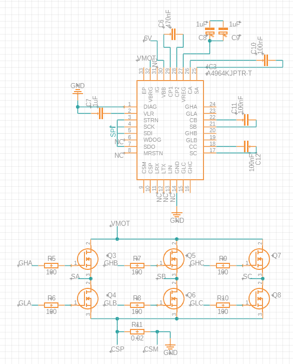
This is the schematic (I am working on a breadboard):

  • Not connected pins are marked with "NC" label
  • Connections from the 3-phase H-bridge to the IC are made with labels
  • Q3 to Q8 are IRLZ44N N-MOSFETs

Schematic

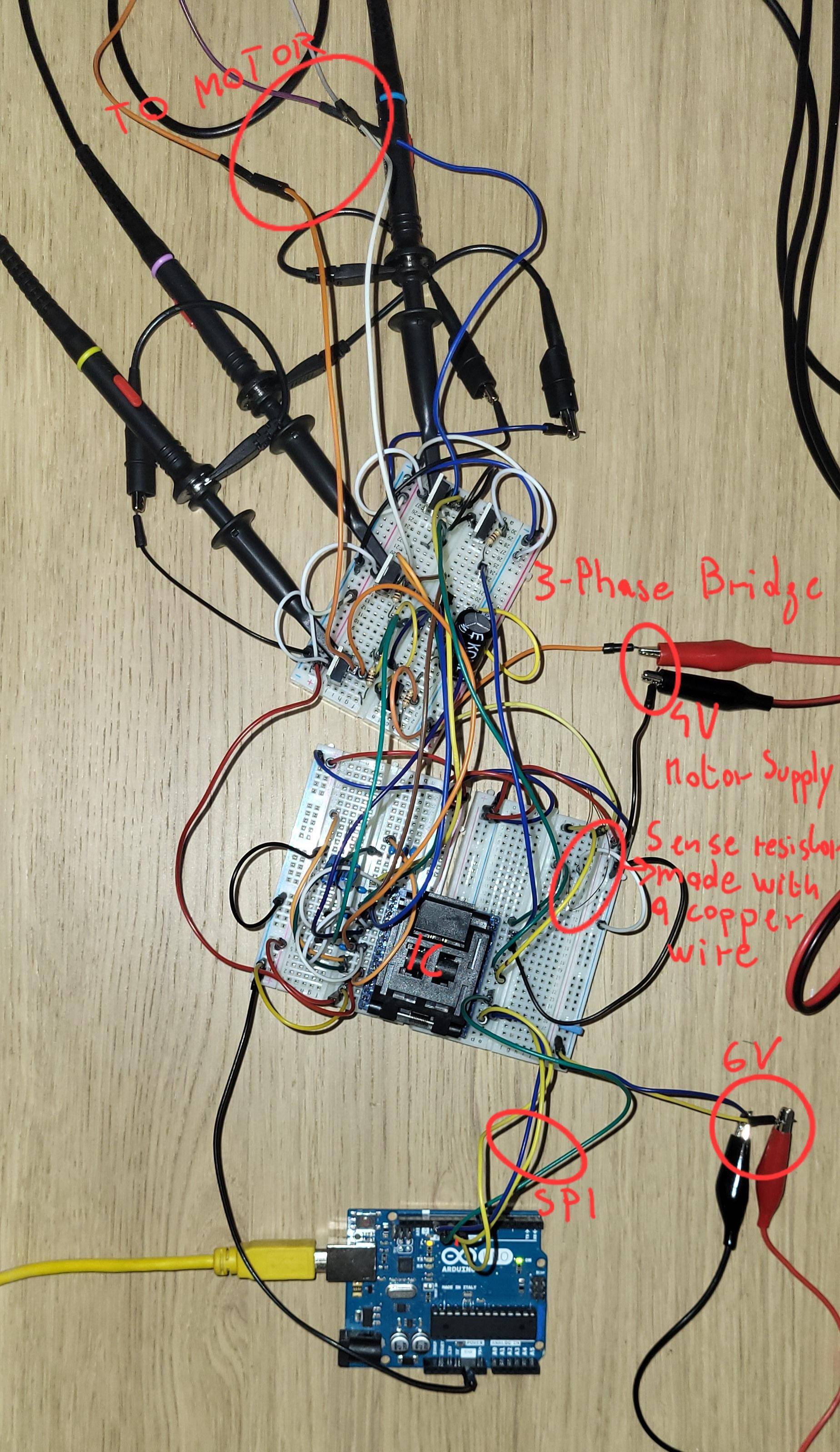
Breadboard connections with notes: enter image description here

The motor phases are connected to SA, SB, and SC. The motor is a small 23000 Kv 0802SE BetaFPV motor, which is powered by a 4 V (VMOT) power supply and the A4964 is powered by a 6 V power supply.

Register settings that I've edited (settings not listed are set to their default value):

  • System register (25): CM[1:0] = 11, open-loop mode
  • Mask register (28): VO = 1 (The chip reports a VDS overvoltage on the C high-side MOSFET and sometimes on other MOSFETs, but it doesn't seem that a VDS overvoltage is actually present)
  • Demand input (30) : 50% Duty Cycle
  • I also tried to lower SF1 to 1.5 Hz, but it only made the vibration stronger and more visible.

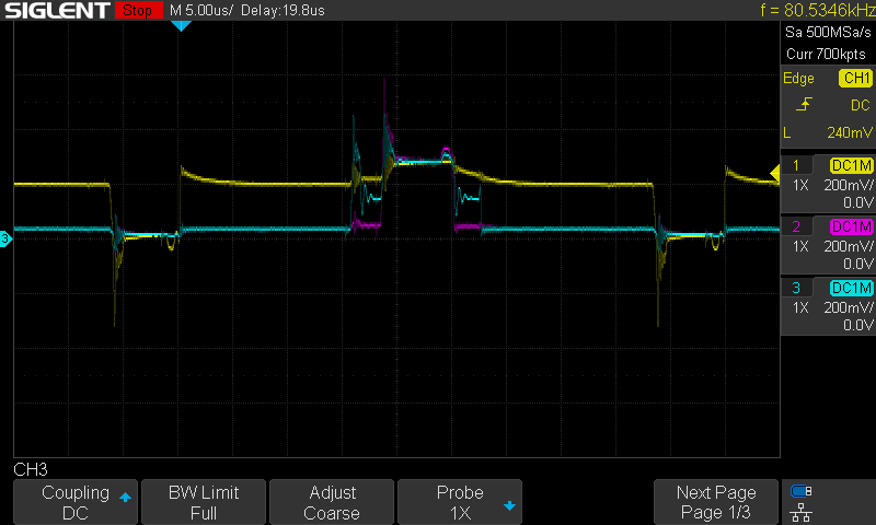
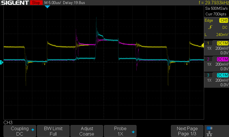
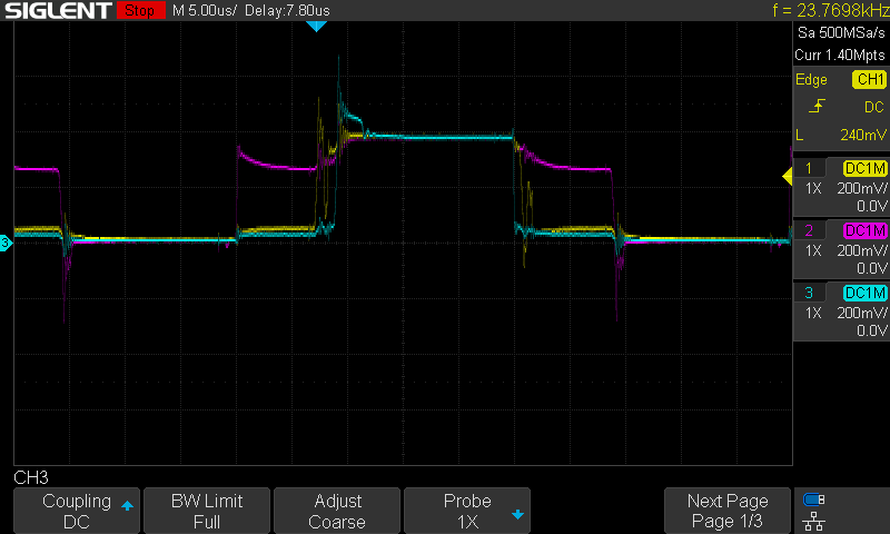
This is the waveform that I get during the "ramp" step (Yellow = A, Magenta = B, Cyan = C, probes are in 10x mode, measuring voltage on Sx outputs):

Immediately after the "Hold" step: After Hold waveform

About half ramp: Half ramp waveform

Nearly at the end of the ramp before getting LOS error: Before LOS waveform

\$\endgroup\$
3
  • \$\begingroup\$ Your schematic as shown does not show the IC. Please edit your question so that it shows the complete motor drive section of your schematic. And, if you're implementing this on a breadboard, please show a picture of that. \$\endgroup\$
    – TimWescott
    Commented Feb 10 at 16:01
  • \$\begingroup\$ In the schematic the 3 bootstrap capacitors are missing and the polarity of the current sense connection is reverse. How ist it on the breadboard? \$\endgroup\$
    – Jens
    Commented Feb 10 at 17:59
  • \$\begingroup\$ I've edited the schematic: added bootstrap capacitors and reversed the sense resistor polarity. \$\endgroup\$ Commented Feb 10 at 18:20

1 Answer 1

0
\$\begingroup\$

The signal and ground plane integrity is atrocious on the breadboards. It will not work - not even close.

You need either to lay out a tight PCB, buy a pre-made motor driver module that uses same or similar chip (preferred), or solder every part's ground pins to a ground plane, say an unetched copper-clad laminate board, and keep things close together. The lines between the driver and the mosfets should be short, less than an inch each ideally, and you'll need good decoupling capacitors etc. You'll need to identify all switching current loops on the schematics, and then keep their area as small as possible on the layout/breadboard.

It is an art to prototype switching power designs, and "breadboarding" them means a solid copper ground plane, not things with holes in them and jumper wires.

\$\endgroup\$
1
  • \$\begingroup\$ So you think that switching to a PCB with a solid ground plane can solve the problem? \$\endgroup\$ Commented Feb 11 at 16:15

Your Answer

By clicking “Post Your Answer”, you agree to our terms of service and acknowledge you have read our privacy policy.

Not the answer you're looking for? Browse other questions tagged or ask your own question.