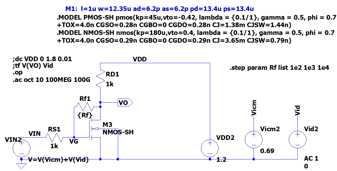
The first is the schematics from NMOS4 with parasitic capacitance:
From DC analysis:
--- MOSFET Transistors ---
    Name:          m3
    Model:       nmos-sh
    Id:          2.21e-04
    Vgs:         8.28e-01
    Vds:         8.42e-01
    Vbs:         0.00e+00
    Vth:         4.00e-01
    Vdsat:       4.28e-01
    Gm:          1.03e-03
    Gds:         2.03e-05
    Gmb:         3.08e-04
    Cbd:         2.32e-14
    Cbs:         3.32e-14
    Cgsov:       3.58e-15
    Cgdov:       3.58e-15
    Cgbov:       0.00e+00
    Cgs:         7.11e-14
    Cgd:         0.00e+00
    Cgb:         0.00e+00
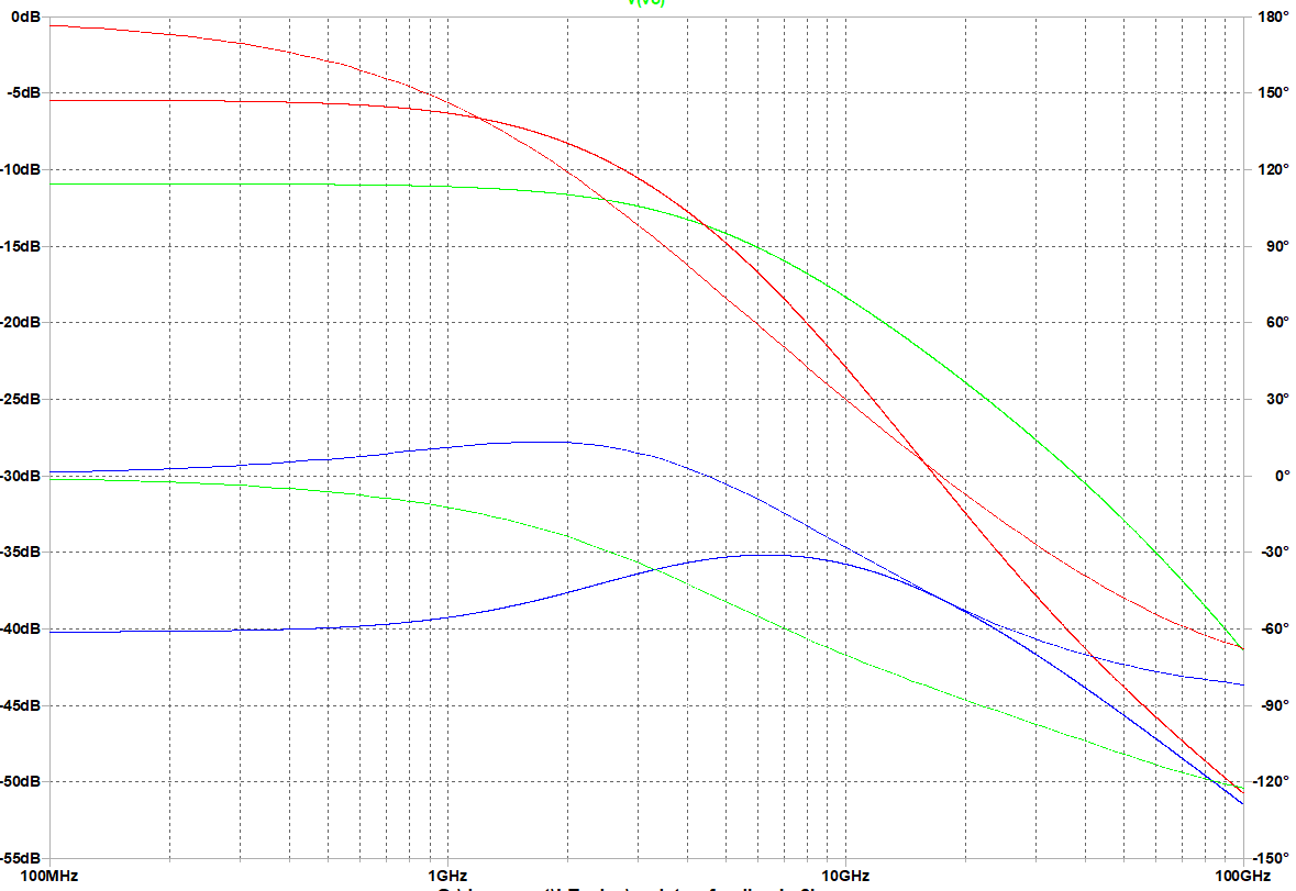
AC analysis:
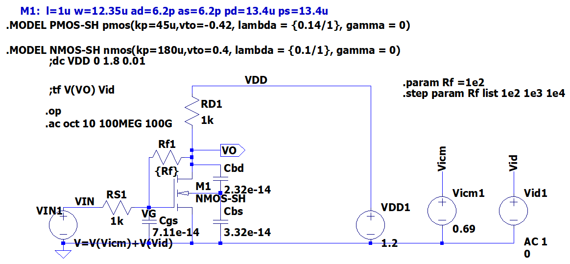
I tried to build an equivalent schematic with my .op analysis for the first schematic:
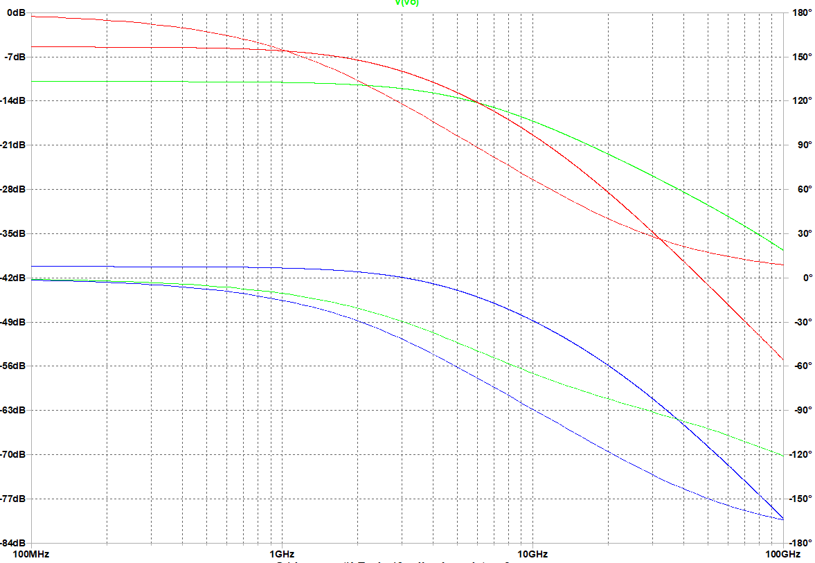
The following is the AC analysis:
You can see these two have significant differences in terms of AC frequency analysis.
What's wrong with my capacitor model?
The following is the asc file for whom is interested:
Version 4
SHEET 1 880 808
WIRE -224 16 -368 16
WIRE 32 16 -224 16
WIRE -368 32 -368 16
WIRE -368 160 -368 112
WIRE -304 160 -368 160
WIRE -368 176 -368 160
WIRE -368 176 -384 176
WIRE -368 208 -368 176
WIRE -304 256 -368 256
WIRE 192 256 192 208
WIRE 352 256 352 208
WIRE -608 288 -656 288
WIRE -576 288 -608 288
WIRE -464 288 -464 176
WIRE -464 288 -496 288
WIRE -416 288 -464 288
WIRE 32 288 32 16
WIRE -368 368 -368 304
WIRE -368 368 -656 368
WIRE -304 368 -304 256
WIRE -304 368 -368 368
WIRE 32 368 -304 368
WIRE 192 368 192 336
WIRE 192 368 32 368
WIRE 352 368 352 336
WIRE 352 368 192 368
WIRE -656 384 -656 368
FLAG -656 384 0
FLAG -224 16 VDD
FLAG -464 288 VG
FLAG -304 160 VO
IOPIN -304 160 Out
FLAG 192 208 Vicm
FLAG 352 208 Vid
FLAG -608 288 VIN
SYMBOL nmos4 -416 208 R0
WINDOW 3 56 60 Left 2
SYMATTR Value NMOS-SH
SYMATTR InstName M1
SYMATTR Value2 l=1u w=12.35u ad=6.2p as=6.2p pd=13.4u ps=13.4u
SYMBOL voltage 32 272 R0
WINDOW 123 0 0 Left 0
WINDOW 39 0 0 Left 0
SYMATTR InstName VDD2
SYMATTR Value 1.2
SYMBOL voltage 192 240 R0
WINDOW 123 0 0 Left 0
WINDOW 39 0 0 Left 0
SYMATTR InstName Vicm2
SYMATTR Value 0.69
SYMBOL voltage 352 240 R0
WINDOW 3 24 152 Left 2
WINDOW 123 24 124 Left 2
WINDOW 39 0 0 Left 0
SYMATTR Value 0
SYMATTR Value2 AC 1
SYMATTR InstName Vid2
SYMBOL bv -656 272 R0
WINDOW 0 -60 23 Left 2
SYMATTR InstName VIN2
SYMATTR Value V=V(Vicm)+V(Vid)
SYMBOL res -368 160 R90
WINDOW 0 0 56 VBottom 2
WINDOW 3 32 56 VTop 2
SYMATTR InstName Rf1
SYMATTR Value {Rf}
SYMBOL res -384 16 R0
SYMATTR InstName RD1
SYMATTR Value 1k
SYMBOL res -480 272 R90
WINDOW 0 0 56 VBottom 2
WINDOW 3 32 56 VTop 2
SYMATTR InstName RS1
SYMATTR Value 1k
TEXT -528 -152 Left 2 !.MODEL PMOS-SH pmos(kp=45u,vto=-0.42, lambda = {0.1/1}, gamma = 0.5, phi = 0.7\n+TOX=4.0n CGSO=0.28n CGBO=0 CGDO=0.28n CJ=1.38m CJSW=1.44n)
TEXT -528 -96 Left 2 !.MODEL NMOS-SH nmos(kp=180u,vto=0.4, lambda = {0.1/1}, gamma = 0.5, phi = 0.7\n+TOX=4.0n CGSO=0.29n CGBO=0 CGDO=0.29n CJ=3.65m CJSW=0.79n)
TEXT -496 -184 Left 2 ;M1:  l=1u w=12.35u ad=6.2p as=6.2p pd=13.4u ps=13.4u
TEXT -688 48 Left 2 !.op\n.ac oct 10 100MEG 100G
TEXT -688 24 Left 2 !;tf V(VO) Vid
TEXT 104 32 Left 2 !.step param Rf list 1e2 1e3 1e4
TEXT -688 0 Left 2 !;dc VDD 0 1.8 0.01


