5
\$\begingroup\$

I have an analog input that I need to measure. The analog input is single-ended and ranges from -10V to +10V.

I want to try and measure that output with an ADC, which has a 0-3.3 V range.

I want -10 V to be 0 V, +10 V to be 2.5 V, and 0 V to be 1.25 V.

Right now, I have -10 V = 5 V, 0 V = 2.5 V, 10 V = 0 V (I can handle just a simple voltage divider to halve the range)

This is the circuit I have now:

schematic

simulate this circuit – Schematic created using CircuitLab

I figure that there's some difference amplifier circuit I can use, but my knowledge of these analog circuits is lacking.

On the board, I have spare op-amps, as well as a 1.25 V reference to use.

Here is an easily editable simulation of the circuit.

\$\endgroup\$
2

5 Answers 5

7
\$\begingroup\$

This resistor divider gets you close:

schematic

simulate this circuit – Schematic created using CircuitLab

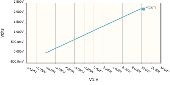
A sweep of V1 from −10V to +10V outputs 0V to +2.22V:

enter image description here

If you want the full 0V to +2.5V, you'll need some gain \$A\$:

$$ A = \frac{2.5}{2.22} = 1.125 $$

In this next design, the op-amp is configured as a non-inverting amplifier with gain 1.125. The overall response to inputs from −10V to +10V is an output going from 0V to +2.5V:

schematic

simulate this circuit

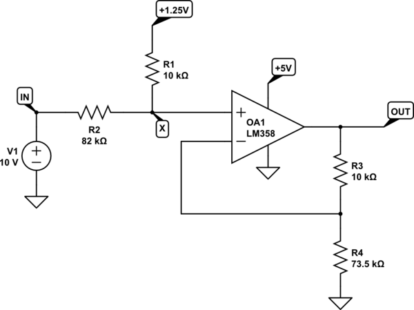
Sadly, that would require a negative supply for the op-amp, because it cannot get all the way to 0V output without one. If you want to use 0V for the negative supply, you'll have to sacrifice a few tens of millivolts at the bottom end.

schematic

simulate this circuit

Note that I've increased R2 slightly, to raise the minimum potential at X to a little over 0V. Since this also increases maximum potential there, I've also had to reduce gain a little. For inputs between -10V and +10V, this last design will output +30mV to +2.5V:

enter image description here

\$\endgroup\$
1
  • 3
    \$\begingroup\$ +1 for showing that some things can be done just using resistors (almost). \$\endgroup\$
    – Aaron
    Commented Feb 20 at 19:28
4
\$\begingroup\$

As per RusselH's (user319836) suggestion below, here's the improved version:

schematic

simulate this circuit – Schematic created using CircuitLab
The output is no longer reversed, but follows the input, except scaled & shifted from -10V ... +10V to 0V ... +2.5V (roughly).


Original Answer below

If you can live with the ramp being reversed, so -10V gets translated into +2.5V and +10V gets translated into 0V, then you can do it with a single opamp.
You could easily reverse it back again in your MCU's code.

schematic

simulate this circuit

The inverting gain of 0.12 isn't perfect, but it gets you to within about 50mV at each end.

The output offset is set by Vref, scaled by R1 & R2, and multiplied by the non-inverting gain: \$1 + \frac{R_3}{R_4}\$, so:

so:

$$ \def\V{{\rm\, V}} \def\k{{\rm\, k\Omega}} % \begin{aligned} V_{ref} \cdot \frac{R_1}{R_1 + R_2} \cdot \left(1 + \frac{R_3}{R_4} \right) &= \\ &= 1.25\V \cdot \frac{10\k}{10\k + 1.2\k} \cdot \left(1 + \frac{1.2\k}{10\k}\right) \\ &= 1.116\V \cdot 1.12 \\ &= 1.25\V \end{aligned}$$

\$\endgroup\$
2
  • 1
    \$\begingroup\$ This is a differential amplifier. Lift R1 from ground. Connect to V1+. Lift R4 from V1+. Connect to ground. Then the polarity is correct. \$\endgroup\$
    – user319836
    Commented Feb 28 at 20:26
  • \$\begingroup\$ @RussellH thx for the hint - updated my answer accordingly. \$\endgroup\$
    – brhans
    Commented Feb 28 at 20:56
3
\$\begingroup\$

Here is a way that uses only two standard values of resistors and your present op-amps.

Note the need for a negative supply for the op-amps, however -5V is adequate. The worst-case output voltage of U1 is -1.25V at +10V input. With your idea of buffering it first, you'd need something like -12V to handle a -10V input. If you don't have a negative rail, you could use something like a 7660 charge pump to generate it from +5V.

enter image description here

\$\endgroup\$
2
\$\begingroup\$

I'd start with reducing the gain using a simple potential divider like this: -

enter image description here

  • negative 10 volts in maps to -1.25 volts out
  • positive 10 volts in maps to +1.25 volts out

enter image description here

So, all you have to do is add an offset like this: -

enter image description here

And, you get what you want.

Of course this task is made easier by using a standard voltage reference such as +2.5 volts and attenuating it to +1.42857 then adding an op-amp buffer before connecting it to R1.

\$\endgroup\$
0
\$\begingroup\$

I want -10 V to be 0 V, +10 V to be 2.5 V, and 0 V to be 1.25 V.

The function you want to implement is

\$V_{out} = (0.125\times V_{in}) + 1.25\$

Since amplification is positive, but less than 1, this can be accomplished completely with resistors and a voltage reference. An op-amp would only be necessary if one wants or needs to counter loading effects. In that case an op-amp configured as a voltage follower can be used.

To solve this problem, we first find a voltage \$V_x\$ that, when given as the input voltage is itself the output voltage. That is,

$$V_x = \frac{1}{8}V_x + 1.25$$

We find this value to be \$\frac{10}{7}\;\text{V}\$.

We also wish to find the voltage \$V_0\$ that, when given as the input voltage, results in a output voltage of \$0\$. That is,

$$\frac{1}{8}V_0 + 1.25 = 0$$.

By inspection, \$V_0 = -10 V\$.

The circuit we wish to implement is of the form:

schematic

simulate this circuit – Schematic created using CircuitLab

To implement the appropriate function we choose resistors with the following ratios:

$$R_{in}:R_{ref}:R_0 \;\;=\;\; V_0(V_x-V_{ref})\;:\;V_{ref}(V_{ref}-V_x)\;:\;V_{ref}V_x$$

We choose the \$V_{ref}=2.5\;\text{V}\$

Substituting and simplifying gives us:

$$R_{in}:R_{ref}:R_0 \;\;=\;\; 12:3:4$$

schematic

simulate this circuit

Then we verify the behavior with a simulation.

DC Sweep

The behavior meets the spec.

\$\endgroup\$

Your Answer

By clicking “Post Your Answer”, you agree to our terms of service and acknowledge you have read our privacy policy.

Not the answer you're looking for? Browse other questions tagged or ask your own question.