1
\$\begingroup\$

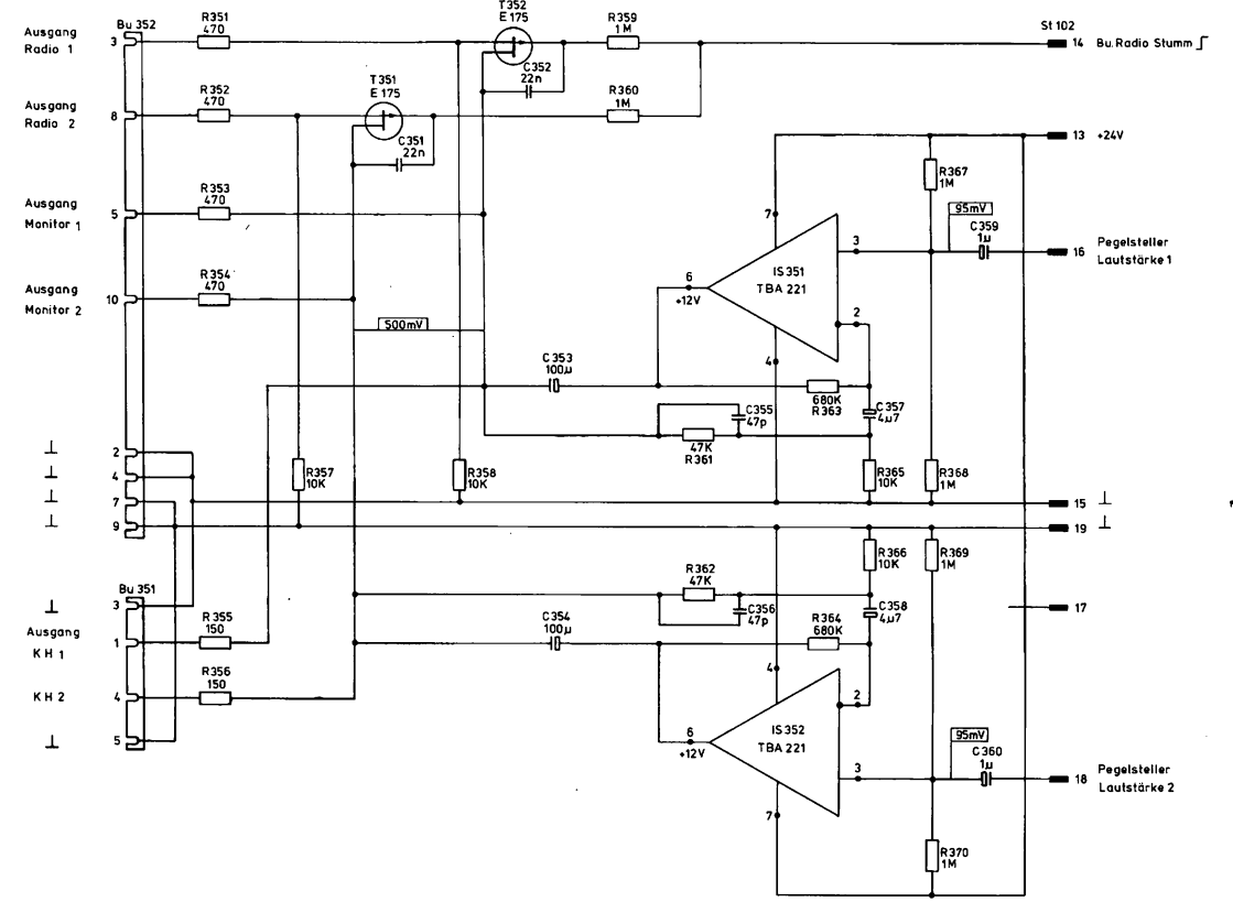
I have a 741-based audio amplifier PCB here from the 70s:

enter image description here

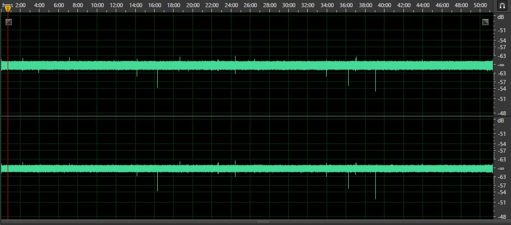
When I tried to test it, I powered it with a 24V battery (I tried 12V as well with no difference,) then I shorted pins 15-19, connected the output to my ADC (analog-to-digital converterm which is together with a laptop running off DC battery) (I tried Arturia Minifuse 4 and tried Zoom H1) and noticed that once every 10-30 minutes there is a sharp spike (pop/click) on a waveform. Sometimes that spike is 15 db louder than the noise floor, sometimes it is 60 db louder. Often these spikes came in pairs with ~2 min interval between them, but overall everything seemed random to me.

I disconnected my ADC and shorted its inputs (to rule out laptop/ADC problem) and there was no problem at all.

Then I tested this circuit on a breadboard (only one channel). I tested it and the problem was there. The same spikes roughly once every 15 minutes.

I tested other op amps (for example, different manufacturers of 741 and also tried LME49710NA) but there was no difference.

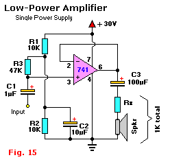
Then I decided to try a different circuit. I tried this one:

enter image description here

The problem was still there.

So I ruled out a laptop, a ADC, cables between them, I ruled out a problem with a PCB, problems with op amp

What can I be possibly missing here? As I am not using any input signal, it's not the "source".

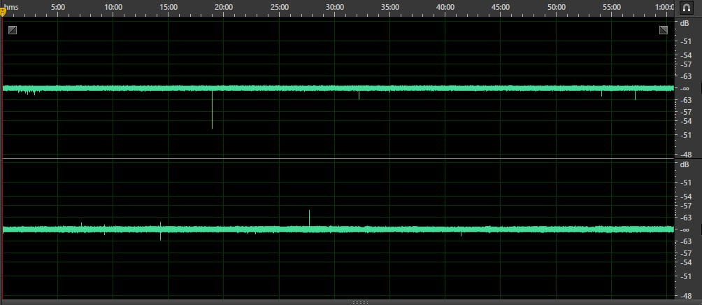
Oh, right, and the power supply: I've tested and it's not related to the problem. Here, take a look yourself. The top channel is audio, the bottom channel is the battery voltage.

enter image description here

A local repairmen told me such problem is not "repairable." Are they correct?

I am sure I did something wrong, but I am tunneling and can't see any alternatives.

UPDATE 1a: I've noticed a small peculiar thing. In my old fridge there is a lever which turns off an inner 15w bulb when you close the door. So when I press that lever sharply, there is a pop/click/spike in a waveform. The distance between my "test setup" and my fridge is 3 meters. The bulb is not 1000w, but just 15w. It's just a bulb after all!!!

  1. I don't understand, what's the connection between the two. My test setup is completely disconnected from the mains. How does that 15w turning on/off 3 meters apart change the processes on a PCB which has only 5.7 gain??? Turning on/off a 3000W IR heater doesn't do anything. That same fridge switching between its modes doesn't do anything to the waveform!!
  2. Shouldn't a regular preamp PCB be prone to such things? I mean that Arturia Mini or Zoom H1 don't react at all to the bulb switching...
  3. It could be some of my neighbours has a home-made xray apparatus or a portable atomic power station which causes these once every 30 (15?) minutes...

UPDATE 1b: I was trying to figure out what's common between the battery, the 70s PCB and my breadboard version. And I thought about... pins. Breadboard has poor pins contact by definition. While the 70s PCB may have something corroded (even though I can't really see this visually; although the pins are not brand-new-shiny). So I've used some contact cleaner on those and maybe (just maybe, I may very well be lying to myself) there was an improvement. And I thought to myself: what if corroded pins have become capacitors??? And that's why they became more prone to some specific EMI which is sometimes in the air? Am I reading too much of science fiction?

UPDATE 1c: This is one of the pops zoomed in (top is left from PCB, bottom is right from PCB): enter image description here
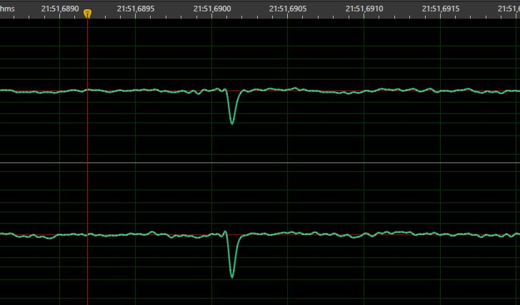
UPDATE 2a: As you advised me to decouple/filter the power supply even more, I've added a pair of 100uF caps between + and - for each opamp. Unfortunately, there was absolutely no improvement. Here: enter image description here
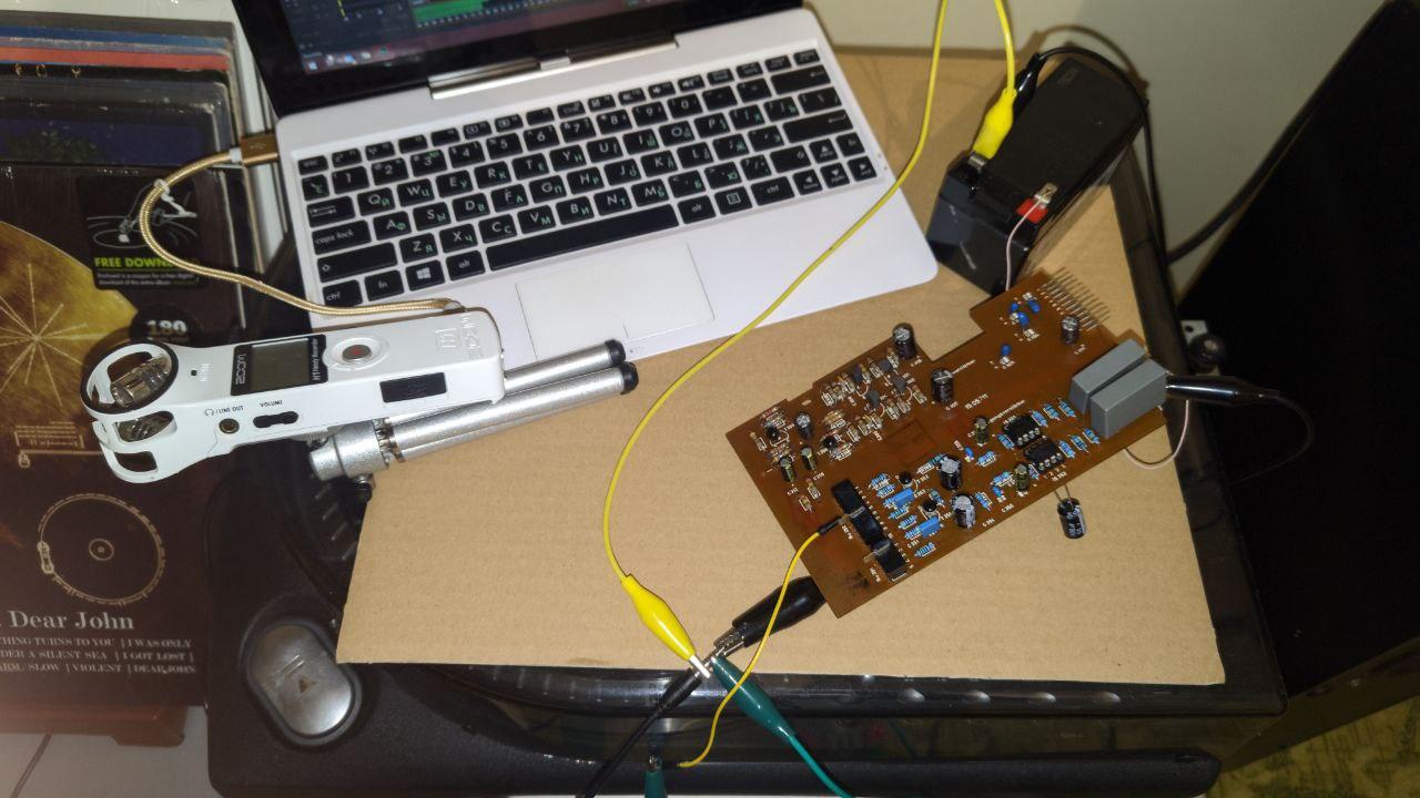
UPDATE 2b: My test setup. Just a plain PCB. All the electricity in my apartment was off at this moment.

  • off battery is soldered to pin 13 (to ensure no contact problems). All other pins are connected to the battery's - via a crocodile clip. Please disregard the top part (unconnected) of the PCB as it is not electrically connected with the pre amp. The designers just made 2 different blocks on same PCB. Thin yellow wire is sticked into left channel's output. And thick black crocodile peeking from underneath is soldered to the right channel's output. On the left side of the image you can see Zoom H1 which acts as an ADC here. Zoom H1 is somehow completely ignorant to all these EMI/whatever things that causes the pops/clicks. Laptop has its WIFI/Bluetooth off as well. enter image description here
\$\endgroup\$
10
  • 1
    \$\begingroup\$ Do you have something like a thermostat switching a load on/off every 10-30 minuted? \$\endgroup\$
    – Justme
    Commented Feb 23 at 18:54
  • \$\begingroup\$ @Justme, no, nothing like that. Also the laptop and everything else is working off battery. That's what I've started with in order to rule out anything related to a mains supply. \$\endgroup\$ Commented Feb 23 at 19:33
  • \$\begingroup\$ Please show the setup. How is the shielding of the circuit and wiring, is the device in a plastic or metal box, are the wires to devices and power supplies a mess of wire loops or organized neatly and shielded? The thing is, the fridge bulb being turned on may have a scratchy switch so it arcs and sparks and the wiring is a loop antenna that radiates the noise. And thus your circuit may be sensitive to such electrical interference, picking up switching of electric appliances and light switches from nearby apartments. \$\endgroup\$
    – Justme
    Commented Feb 24 at 12:05
  • 1
    \$\begingroup\$ Lack of decoupling/filtering and PSRR. \$\endgroup\$
    – winny
    Commented Feb 24 at 12:07
  • 1
    \$\begingroup\$ Congrats about finding the culprit. If I was fighting this with my own hands, I would probably be stumped. Thanks for educating me :-) I have faced some mysteries too, in the past - some I have solved, some I have not. That's an interesting bit of information that you've brought here. \$\endgroup\$
    – frr
    Commented Mar 1 at 20:09

2 Answers 2

1
\$\begingroup\$

You have some spikes on the battery voltage as well!

Can you think of some way to verify if the spikes are really there, in the analog signal? Such as, run the output into an active loudspeaker?

You seem to have a digital recording... what do the spikes look like up close = zoomed all the way in, over a span of just a few samples? I believe analog glitches would look different from some problem in the digital data path.

Your ADC appears to be a USB thingy (endpoint). Probably connected to a computer. What sort of computer? Is that a PC? If that's a PC, do you have any clue if C-states (the link points to a piece written by me on behalf of my employer) deeper than C1e are enabled? There tends to be an entry for that in the BIOS, among the CPU properties / CPU power management...

Might be other things in the computer, apart from C-states. See also. If there's a suspicion about the CPU going out to lunch every now and then, LatencyMon is your friend (Windows).

You might also try to pick up some EMI from the ether deliberately. I'd take a section of some kind of wire or "conductor" that I have around, and either wind a couple dozen loops around some suitable non-metallic frame, such as a laundry basket, or maybe a single huge loop around the room - and plug that into the input of the ADC. Yes you'll probably pick up quite a bit of mains hum. But, there might be some glitches as well.

These tips should help you decide, if this problem is analog or digital.

Hmm... perhaps your audiophile ADC is adding some vintage gramophone pops and snaps? ;-)

EDIT - regarding the light bulb:

A light bulb is not a resistor. When cold, it has maybe 5% to 10% of its "nominal" resistance. The "nominal" resistance of the filament only gets achieved when the bulb is shining. Therefore, bulbs produce a nasty glitch on power-up. A circuit breaker will ignore it by its inertia, but if you put a shunt resistor in series and attach an oscilloscope to watch it, you will see the cold-start spike clearly there. It lasts just a couple milliseconds, probably far less than a half-wave of the mains sinewave.

From there, free-space electromagnetic induction is a pig :-) Δi / Δt has some effect, and the amplitude of the spike is randomized by the precise point on the mains sinewave voltage where you switch the bulb on. Not sure what your PCB looks like and what your wiring from the battery to the amp looks like. Watch the area of the loop between the leads going from the battery to the amp. If they are loose conductors, try to put them closer together. And, block the rail by an elyt cap close to the op-amp, as suggested in a comment.

EDIT: so we're back to analog ghost-busting...

I'm afraid it's not a matter of trying a different op-amp chip. The chip is tiny, and per se receives hardly any EMI. It's the circuitry around that needs to be tackled first. Different op-amp and audio amp chips may nominally feature different levels of inherent "power supply rejection ratio", but that's after you've done all you could at the board level / wiring level. And I'm afraid so far you've just scratched the surface here :-(

How do you combat EMI, in general (not all the advice may be compatible with your circumstances):

  • make the live signal conductor closely aligned to its respective reference ground conductor. I.e., use a straight twin-wire cable, or a coax, or a twisted pair, or a shielded twisted pair :-)

  • if you're figting glitches coming via the power supply, which in your case is a battery, apply the same advice to your power cabling as well = use a twin-lead cable from the battery to the circuit board. This shrinks the loop area, compared to what I see on your photo.

  • split-supply op-amp topologies tend to have a better PSRR compared to single-supply topologies (and other advantages). But you probably won't convert an existing amp circuit from single supply to split supply.

  • the PCB should have a ground plane (= needs to be double sided) and should minimize loop areas between the amp chip and any power+return paths.

  • note that in split-supply power topology, the + and - power inputs (filter capacitors, really) take turns working against the center ground... ehh. Kind of difficult to picture. Just avoid making large loops on the power paths, and on the signal paths. Having a ground plane helps here a lot :-)

  • put the circuit board into a metal enclosure. It's a good question how and where to connect the grounds/earths together. Maybe start by earthing the PCB to the chassis at one spot, perhaps close to the PCB terminal that you're using for the power ground. For safety reasons, if your circuitry is powered by the mains, your metal enclosure should be earthed to the Protective Earth... (which may or may not bring more EMI into your signal paths)

  • consider making your signal inputs differential (+ provide a reference ground) = shielded twisted pair

  • in theory, you should avoid ground loops, between the Protective Earth and your signal reference grounds... which is a sick inside joke, once you understand what's mandatory by safety norms and e.g. what the notebook PSU does (how noisy it is) :-)

  • you can also retreat from maximalistic virtues, admit an earth loop via PE and signal reference ground... and maybe implement differential input, where your ref.gnd is not attached to chassis gnd at the line receiver...

  • if the signal at hand allows this, you can break the pesky grounds by deliberate isolation - using a signal transformer, or by optocoupling the signal, or by going digital as close to the analog source as possible (think digital microphones, digital sensors). I can't see you achieving this in analog audio in the case at hand :-)

  • if you know the particular source of your EMI, you can try to muffle that source = dampen the radiation in the first place. Insert an EMI filter in the mains lead of your fridge (if not inside).

  • EMI radiates through open space by magnetic induction, by electrostatic coupling (capacitive), and travels over wires. The precise mechanism is not always immediately obvious - or it's not immediately obvious, which of the three ways is biting the hardest in your particular scenario :-)

Weeding out EMI can be difficult, and there are no silver bullets, no simple and cheap recipes. Not sure what your motivation is, how much pressing your issue is that you're trying to solve, how much time you have for the ghostbusting activity, to what extent you are enjoying this etc. None of my business :-) the choice is yours.

If I should suggest to start from the basics, which you have already hinted at, and you are on the tinkerer side, you might be interested in my earlier inside project (the link points to my personal hobby website) - a handful of universal boards for playing with the basics of op-amps and discrete transistors. Intended for cases where a breadboard is no longer enough, but designing a dedicated PCB and having it made seems a tad far fetched. I mean - this would give you a ground plane on the PCB, and the power is relatively well filtered too. Not sure if you're advanced enough to appreciate this sort of thing :-) or if this is aligned with the direction you're heading etc...

Also, a while ago, I've made a simple gadget that picks up electrostatic and EM interference deliberately, amplifies it and feeds it into headphones - intended as a detector of live cabling in the walls. But I still only have it in the form of a tinker-board prototype, I don't even think I have a proper schematic... Maybe someday I turn this into a PCB. This linear EMI pickup gadget tells me that the ether can actually be pretty noisy :-) i mean inside buildings, even relatively far from mains wiring.

\$\endgroup\$
9
  • \$\begingroup\$ I absolutely loved the last statemend :D Well, I've both tested that ADC+laptop with inputs shortened over a long period of time, and also that ADC+laptop with input from my phone outputing a silence track. So I am 100% we can rule out the digital domain things. And that's exactly why I think the CPU-related stuff can also be disregarded. Please correct me if I am wrong. Regarding EMI: well, I have here a very-very-very old fridge, which when turns on/off creates a loudest possible spike in loudspeakers. But the moments it turns on/off never correlate with spikes described above. \$\endgroup\$ Commented Feb 23 at 20:23
  • 1
    \$\begingroup\$ Oh, and I tried to turn off literally EVERYTHING in my apartment, to no luck and no difference. \$\endgroup\$ Commented Feb 23 at 20:23
  • \$\begingroup\$ You know... it was clever of you to record the output of the amp and the PSU, correlated in time. From that recording, it's weird to me that the spikes do not overlap in time! You are somewhat right that if recording analog silence produces no spikes, this implies lesser chance of a mischief in the digital path. That said, you don't have certainty. BTW, what is a silence track? Is that digital zeroes to the DAC, or is that some minimal volume of noise? Could you perhaps try recording some level of noise or a sinewave? \$\endgroup\$
    – frr
    Commented Feb 24 at 9:08
  • \$\begingroup\$ In a very different scenario, I had such random spikes in data, captured by a counter (rotary encoder). They were just one digital sample wide, and then back to the correct value. Turned out the encoder hardware had a HW problem, an "unhandled critical section" when reading from the working counter and pasting that value into a further communication path. It takes some time to flip a cascade of bits in a binary counter, and if the value was latched halfway during that cascaded increment, you'd get a sample that's way off in either direction. Larger errors were statistically less frequent. \$\endgroup\$
    – frr
    Commented Feb 24 at 9:16
  • \$\begingroup\$ I'd be a little surprised if a modern audio ADC would be running asynchronous to the output sampling rate and would be prone to this kind of latching collision. I'd also be surprised if two very different off-the-shelf gadgets were using the same buggy codec (ADC). But anyway this was my reason to ask about a macro view of some of those pops and clicks in the sampled data. If you're recording silence, chances are that such latching collisions (with a cascade of bits flipping in a counter or a successive approximation ADC) are rare or produce only a small glitch = get hidden from view. \$\endgroup\$
    – frr
    Commented Feb 24 at 9:26
1
\$\begingroup\$

Solved by using an Op Amp with EMIRR (EMI Rejection Rate). I used TL071 and the clicks were almost completely gone.

P.S. OPA1641 didn't help at all, even though its EMIRR should be much higher. Probably I got the fake chips. I am a newbie in this, so finding out the chips can be fake was a big surprise to me...

\$\endgroup\$
2
  • \$\begingroup\$ If you have not been buying your chips from a reputable distributor like DigiKey, Mouser, Allied Electronics, ELFA-Distrelec, and such, you are wasting your time and energy. Do not buy any chips on Amazon or AliExpress unless you’re an expert who has the means to ensure they got usable parts. And even experts get fooled sometimes. \$\endgroup\$ Commented Mar 1 at 14:36
  • \$\begingroup\$ Amazing. Thanks for the report. I wouldn't believe this :-) Seems to me that the clicks are arriving from outside via the power supply conductors, and an op-amp with not enough PSRR just couples that interference to the output. Or something. Heh the venerable TL071. Who would've guessed :-) Taking a look with an oscilloscope would certainly be interesting, but to a typical hobbyist a decent 'scope is over budget. I myself am lucky to have one at work. \$\endgroup\$
    – frr
    Commented Mar 1 at 20:01

Your Answer

By clicking “Post Your Answer”, you agree to our terms of service and acknowledge you have read our privacy policy.

Not the answer you're looking for? Browse other questions tagged or ask your own question.