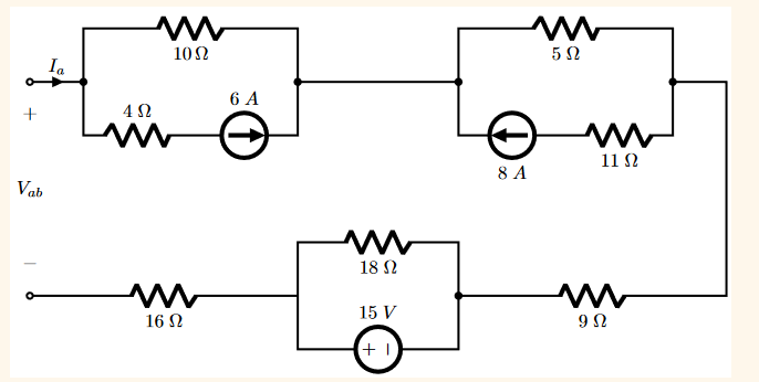
In your example, you know you got \$-35\:\text{V}\$ and, when a \$10\:\text{V}\$ source was connected you then got \$1.125\:\text{A}\$. So the Thevenin resistance is \$\frac{10\:\text{V}-\left(-35\:\text{V}\right)}{1.125\:\text{A}-0\:\text{A}}=40\:\Omega\$. And that's right.
Andy is also quickly telling you the right of it.
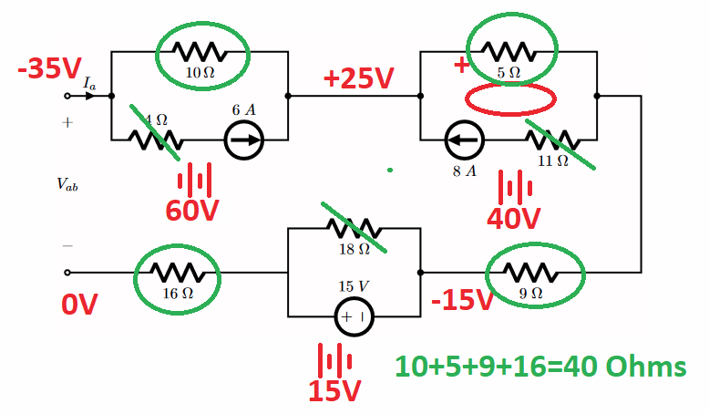
Here is how to quickly use your diagram to see the essentials:

The red color is for Thevenin voltage.
The green color is for Thevenin resistance.
Current sources are infinite resistance. So any resistance in series with them is taken as 0 Ohms. (I'll explain why in a moment.)
Voltage sources are short circuits. So resistance in parallel with them is taken as 0 Ohms. (I'll explain why in a moment.)
The current source loops cause their parallel resistance in the loop to generate a voltage.
Another thing to note is that there is no current taking place between the + and - points of \$V_{ab}\$. So any remaining series resistors that contribute to the Thevenin resistance, around the loop, will therefore have zero voltage drop across them.
Working around the loop, starting at the bottom and taking it as \$0\:\text{V}\$, there's no voltage drop across the \$16\:\Omega\$ resistor (no current through it), there's then a \$-15\:\text{V}\$ drop due to the voltage source, no voltage drop across the \$9\:\Omega\$ resistor (no current through it), then a \$+40\:\text{V}\$ rise due to the voltage difference generated across the \$5\:\Omega\$ resistor by the \$8\:\text{A}\$ current source, and then a \$-60\:\text{V}\$ drop due to the voltage difference generated across the \$10\:\Omega\$ resistor by the \$6\:\text{A}\$ current source. This all sums to \$-35\:\text{V}\$ at the other end of the loop.
The resistance is then the sum of the remaining series resistors. That's \$40\:\Omega\$ in total.
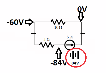
Now, the reason why a resistor in series with a current source can be taken as \$0\:\Omega\$ is simply because the voltage across the current source (which you probably weren't thinking about) automatically adjusts itself to the circumstances. So, let's take the loop in the upper left corner of your diagram. Here, there is \$6\:\text{A}\$ pointing to the right. This means the most positive end of resistors around the loop will start with the end of the resistor where the arrow points into -- the \$10\:\Omega\$ resistor. That also means that the right side of that loop is the most positive side. As the \$6\:\text{A}\$ goes through the \$10\:\Omega\$ resistor it generates a \$60\:\text{V}\$ drop. So the left end of the \$10\:\Omega\$ resistor will be \$60\:\text{V}\$ less than the right end. Now, there will also be a \$24\:\text{V}\$ drop across the \$4\:\Omega\$ resistor, with the more positive side of that resistor being on the left and the more negative side on the right. So look at the following diagram:

Note that the current source automatically causes itself to have \$84\:\text{V}\$ across it, oriented as shown.
Now, suppose you changed that \$4\:\Omega\$ resistor into a \$2\:\Omega\$ resistor? Then the current source would automatically develop exactly \$72\:\text{V}\$ across it to compensate.
In short, no matter what value you stuff in there, the current source adapts immediately to that change such that the voltage across the \$10\:\Omega\$ resistor stays unchanged, as it must.
So you can just short the \$4\:\Omega\$ resistor out and be done with it.
As far as the voltage source goes, the voltage source will always ensure exactly \$15\:\text{V}\$ across it, oriented as shown. So the current in the \$18\:\Omega\$ resistor is known and cannot change. No matter how much current is sent through the loop, any current left over after taking into account the known, fixed current in the \$18\:\Omega\$ resistor must go through the \$15\:\text{V}\$ voltage source. It adjusts its current to pick up all current changes through the loop. In effect, it acts like a short to variations in current around the loop. So the \$18\:\Omega\$ resistor cannot contribute to the loop resistance as current changes are bypassed around it by that voltage source. Or, put another way, the voltage source sets the current in the \$18\:\Omega\$ resistor and any difference between loop currents and that fixed, set current in the \$18\:\Omega\$ resistor are simply bypassed through the voltage source, instead.


