1
\$\begingroup\$

I am in the design phase of building a simple axial flux permanent motor, and I am wondering if I should use a piece of tempered glass as both an insulating material and as part of the motor's frame.

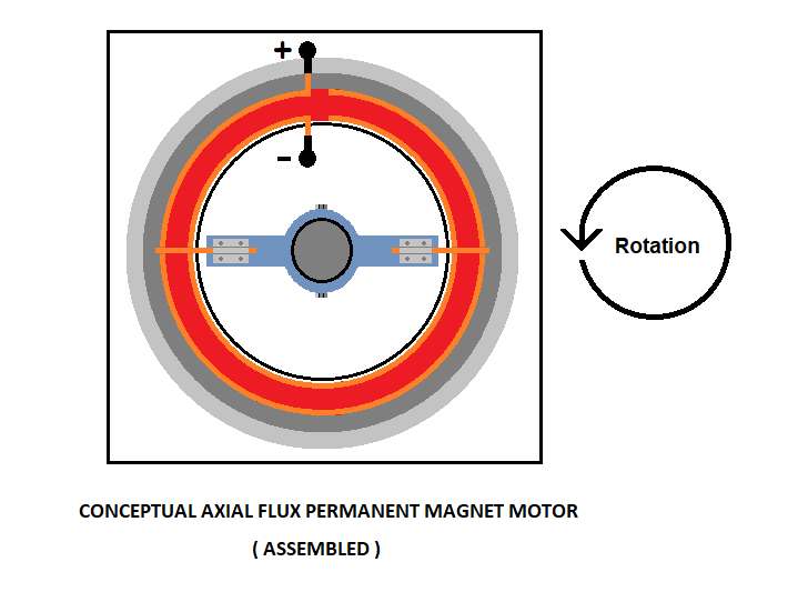
To illustrate the working principle of this conceptual DC electric motor, I have created three conceptual drawings. The first drawing shows two of the primary parts of this motor. The second drawing shows the other two primary parts of this motor. The third drawing shows the assembled primary parts of the motor.

enter image description here enter image description here enter image description here

The purpose of using a pot magnet is to minimize the magnet's magnetic field within the interior area of the pot magnet so the rotor and the armature will not be slowed down by it and/or be heated up by it from resistive heating.

I am planning to fasten the circular rails (which will be made using bare 8-gauge solid core copper wires) to the piece of tempered glass using a strong metal-to-glass adhesive. The tempered glass will insulate the electrified circular rails from the pot magnet. Also, the two short pieces of bare wires attached to the armature will also be 8-gauge solid core copper wires.

The two bare copper wires on the armature will slide along on the bare copper circular rails, this direct contact will provide a path for the DC electrical current, and the magnetic interaction between the two rails and the two wires on the armature, along with the magnetic field of the pot magnet, will propel the two wires in a counter-clockwise direction and this will result in rotating the motor's rotor.

An unwanted side effect of this magnetic interaction is that the two rails will repel one another. I am concerned that this repulsion may become strong enough to break the adhesive bond holding the circular rails to the tempered glass if the electric current were to get too high. I think that this could also result in the tempered glass breaking/shattering and this is then a safety issue.

At this point, I do not know what other material that I could use in this motor other than using glass. The benefit of glass is it can take a lot of heat and it is also an electical insulator. This motor will get hot from the friction of wires rotating on wires and also depending on how many amps are run through the wires. I am thinking that this motor can only be run for short periods of time, perhaps for about two minutes or so, and it will then need to be shut off for a short time so the copper wires can cool down.

I am hoping that if someone here on Electrical Engineering.SE agrees that using tempered glass is not a good material to use for this type of motor, that he/she will suggest a different material to use instead of the tempered glass.

Would tempered glass be a good material to use within this simple axial flux permanent magnet motor?

\$\endgroup\$
7
  • 1
    \$\begingroup\$ Seems to be a low-efficiency homopolar design. Have you considered wide, brush type contacts, instead of sliding wires? Epoxy and phenolic polymers are readily molded, strong when reinforced with fibers, do not shatter when damaged, and are effective up to fairly high operating temperatures; have you considered them? \$\endgroup\$ Commented Mar 2 at 0:55
  • \$\begingroup\$ @TimWilliams, no, I haven't considered those materials. I will do some research on them. \$\endgroup\$
    – user301910
    Commented Mar 2 at 0:57
  • \$\begingroup\$ @TimWilliams, I have thought about using wide, brush type contacts, yet I don't know if that would be a good idea due to issue of centrifugual force. I think those brushes may come flying off the armature after a certain period of time. \$\endgroup\$
    – user301910
    Commented Mar 2 at 2:27
  • \$\begingroup\$ Well uh, how would you be fixing them in place? And just how fast are you thinking? Beryllium bronze (a common choice for brush material) is as strong as steel, you'd have to get the thing going pretty damn fast to cause that to tear off, even if it's just riveted in place. Anyway, if you're trying for high speeds, a homopolar design isn't a good candidate. These days, a 1 or 3 phase BLDC is probably the best bet? \$\endgroup\$ Commented Mar 2 at 2:50
  • 1
    \$\begingroup\$ @user57467 You say it's an experimental design so, why not conduct an experiment to find out? \$\endgroup\$
    – Andy aka
    Commented Mar 2 at 10:19

1 Answer 1

0
\$\begingroup\$

This is more of a materials question. Materials are an important part of electronic equipment, but you may find more and better answers on the Engineering Stack.

Glass is a poor choice here, as it's hardly machinable, is sensitive to sudden changes in temperature (assumed: arcing), and isn't especially strong. Low-expansion types such as borosilicate or even fused quartz, are available, but are harder to work, and more expensive.

Tempered glass is almost certainly out, as tempering (freezing the surface faster than the core to lock in compression in the surface and tension in the core), can only be applied to whole pieces, largely flat and simple shapes. I don't know enough about tempering to say whether a part of this shape can be produced, but you almost certainly will not be able to machine (read: grind) it to an exact shape, not only because it deforms as that locked-in stress is partially relieved upon cutting the surface (compare: machining cold-rolled metal), but as is particularly notorious for tempered glass, any significant defect results in a cascade failure as the whole item shatters into a thousand bits.

Common choices for engineering materials include fiberglass reinforced epoxy or phenolic resin, available with quite reasonable operating temperatures (e.g., PCBs withstand soldering temperature, albeit not bearing much force at such temps). FR-4, G10 and other materials are cheap and abundant, and readily machined with carbide tools (or HSS in a pinch, if you don't mind dulling them quickly). There are also silicone and ceramic cements of varying strength and working temperature range.

You may not need any insulation at all. Ferrite magnets aren't particularly conductive, and the operating voltage is probably only ever going to be a few volts, if I make a ballpark guess at the speed and scale of this machine. Little current is shunted through such material.

Once you have exhaustively determined that heating is inevitable (i.e. the sliding contact or slip rings cannot be improved further), you may consider more advanced engineering materials. For example, the stator rings could be copper rings/collars/plates brazed onto, or pressed into, an alumina or other ceramic insulator substrate, into which the magnet is fitted. Water cooling passages can be embedded within either material, and rotating couplings can be used to cool the rotor. Copper-loaded tungsten might be used to increase abrasion resistance, or copper-loaded graphite for lubrication.

There are also softer, but better machinable, ceramic materials, such as Macor. Not terribly cheap IIRC, but effective for high temperature prototyping.

Also don't ignore sheet insulation materials. Airgap must be kept to a minimum for the magnets to do the most work. (I assume you also have steel pole pieces returning flux around the magnets.) Tough sheet materials like polyimide "foil", fiberglass, Nomex or Kevlar textile or composite, etc. are available. Fiberglass sheet and mica paper (dry, no resin) are available with very high operating temperatures, though not much abrasion resistance given their fibrous or soft nature.


Most of all, though: don't commit premature optimization. Don't care about materials. Use glue, epoxy, paper, ABS; use aluminum or even iron conductors for all that matters. Solve everything else first. Minimize air gap -- use pole pieces, maximize cross-sectional area, maximize conductor width and optimize thickness, maximize brush contact area. To do all this, you need small prototypes that are easy to machine, iteration after iteration. You don't need brittle unworkable materials with high performance. Make a bad motor first. But make it the best damned "bad" motor you possibly can. Then make it "good" with proper choice of materials.

Only then: determine operating parameters, design torque, speed, voltage; mechanical outline / aspect ratio; and scale the mechanical design to that. Voltage determines insulation; you will likely find little is required for a motor of this type (like I said, single volts perhaps). Likely you can optimize performance enough to get efficiency usefully high (>80%?), so that high-temperature materials and water cooling aren't required, or not until higher power levels (kW+?).

Good luck!

\$\endgroup\$
1
  • \$\begingroup\$ I agree with you that tempered glass or any glass is the wrong material to use for this type of motor. I will consider using the other materials that you have recommended. It will take some time for me to research them and then for me to consider how much that I want to spend on building a prototype. \$\endgroup\$
    – user301910
    Commented Mar 5 at 1:00

Your Answer

By clicking “Post Your Answer”, you agree to our terms of service and acknowledge you have read our privacy policy.