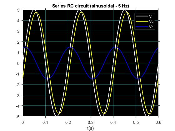
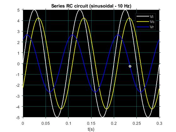
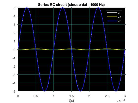
For intuition regarding this behaviour, it might be easier to consider capacitor voltage rather than current, and then relate that to current through both resistor and capacitor. The voltage \$V\$ across a capacitor is:
$$ V = \frac{1}{C}\int{I \cdot dt} $$
That is, for any given current through the capacitor, the voltage is going to rise (or fall) at a rate proportional to that current.
Now consider that the time between peaks of higher frequency signals will necessarily be less than for lower frequencies. That means that the capacitor voltage has less time to "integrate", less time during which it can rise (or fall). Therefore, at higher frequencies, you can expect smaller amplitude voltage variations across the capacitor.
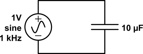
This is easy to see when one directly drives an alternating current through a capacitor. Using square wave current sources of equal amplitude (±1A), but at different frequencies, we can compare how capacitor voltage differs:
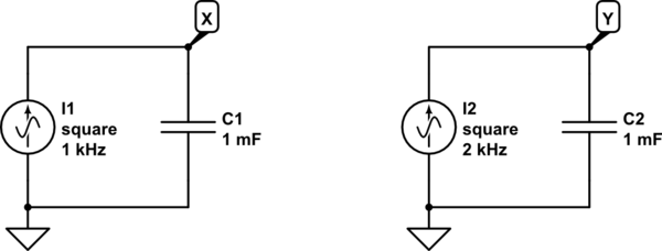
simulate this circuit – Schematic created using CircuitLab
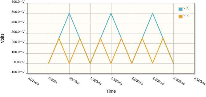
You can see how the "slopes" (rate of change of capacitor voltage) are identical, but one of the capacitors simply has more time between instants where current changes direction, in order to accumulate charge.
It's fair to say, then, that the amplitude of voltage signal across a capacitor is inversely proportional to frequency of current through it.
Returning to the RC circuit, you must realise that whatever voltage exists across the capacitor is voltage that isn't across the resistor. That's KVL at work; the instantaneous sum of resistor voltage and capacitor voltage is equal to the source voltage.
At lower frequencies, the capacitor's voltage amplitude is greater, and therefore resistor's voltage amplitude is reduced. At higher frequencies, it's the other way around, the resistor gets the lion's share of the source's voltage.
Therefore, since it is the resistance that determines current, as frequency increases, and resistor voltage amplitude increases, peak current will increase.
This is a very contrived explanation, and I'm not super happy with it, but that might be good enough. However, you must also consider that in your own example, the source is sinusoidal, smoothly changing between positive and negative values. This adds another consideration: by the time capacitor voltage has peaked, the source voltage is already on its way back down again, which will necessarily influence the peak voltage attainable by the capacitor. That's very hard to describe purely intuitively, and it only becomes clearer (in my opinion) when examined mathematically.
I can't think of a way to describe this response to a sinusoid other than to say that the total source voltage available to be shared between both resistor and capacitor is changing continuously, which not as trivial to envisage or explain, compared to if the source were square. Suffice to say that you must consider this too; you can't just assume that the maximum voltage across the resistor coincides with the minimum voltage across the capacitor, or with peak source voltage, as you could with a square wave.
More pictures to illustrate:
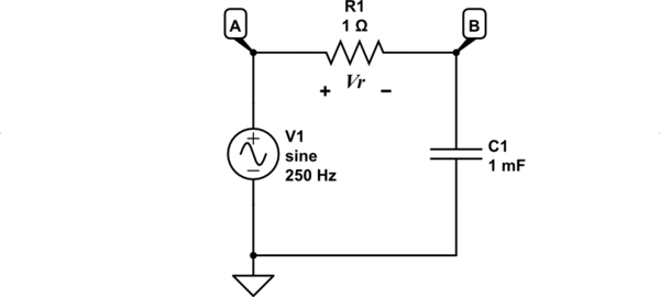
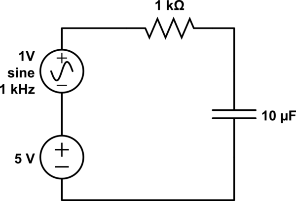
simulate this circuit
Here is a plot of source voltage \$V_A\$ and voltage \$V_R=V_A-V_B\$ across the resistor:
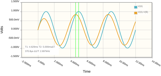
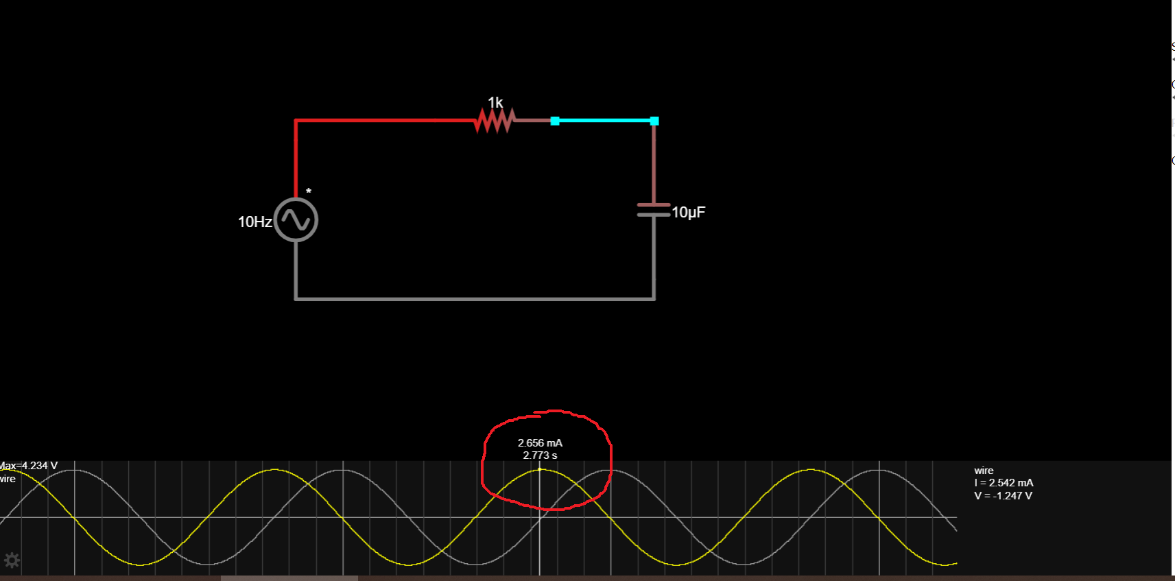
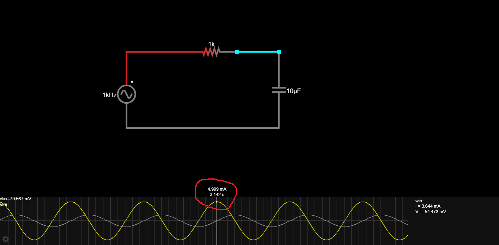
It's important to notice that the peak voltage across R1 (corresponding to peak current) does not coincide with peak source voltage. For this reason it is inappropriate to assume that maximum current should be the same regardless of frequency, since that varying frequency is also causing a phase shift which separates those peaks in time.
One thing I find myself repeating, is that when you apply KCL and KVL and Ohm's law to these circuits, what you end up with is a set of simultaneous equations, and the word simultaneous is not there for nothing. It implies that at any instant in time, there is only one solution for all parameters, impedance (resistance), current and voltage.
You wouldn't be wrong, therefore, to say that those three things aren't actually different things, since their values are intimately related. It might be better to think of them all as different measurements, different "aspects" of the same underlying thing, electricity, three sides of the same three-sided coin, if that makes any sense.
The issue with trying to get intuition about even simple circuits involving capacitors and inductors, is that not only does everything depend on everything else, all at once, there is now an added variable, time. The capacitor here is developing a voltage which is not only dependent on the current through it, but also the time for which that current has been passing. The introduction of time into the equations means that there are now three variables: voltage, current, and time. I omit impedance, since that's just the ratio of voltage to current.
Capacitors and inductors consequently, introduce behaviour that is not just a function of current and voltage, but also of time, and this produces delays and other time-related phenomena, such as the phase shift between current through and voltage across them.
The fact that the capacitor's current is not in phase with its voltage (and vice versa) means that the voltage across the capacitor is not (necessarily) in phase with the voltage source. Consequently, resistor voltage which is dependent upon both, will not be in phase with the voltage source or the capacitor! You find, then that every single element's voltage is out of phase with every other, and that's enough to have me throw my hands up in resignation, and revert to just trusting in the maths.

