1
\$\begingroup\$

I had a follow up question to this: How does a magnetic material "confine" a magnetic field?

In the above question, it asks how the magnetic flux is "confined" by the core. The answer is that the actual H field produced by the primary side is constant regardless of the presence of the core, but the high permeability causes a lot of magnetic flux density to occur in the core (as opposed to outside of the core, where the lower permeability causes less flux density in response to the H field.)

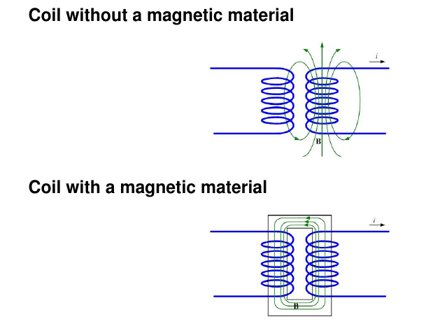
How can you assume (for most transformers) that most of the flux going through the primary also goes through the secondary? Yes, I know that there is some leakage flux, but for the most part, transformers are said to be very good at having most flux thread through both the primary and secondary.

As is the case for most coils (as I understand it,) the H field created by the primary side would be strongest in its centre, and weaker and points further away, so the H field would also be weaker in the centre of the secondary. Since the permeability of the core is constant, the H field is magnified by a constant amount in the primary and in the secondary, the degree by which the H field is stronger in the primary than secondary is the same degree by which the B field is stronger in the primary than secondary.

If that is the case, then how is it said that most of the flux density in the primary is also shared with the secondary?

enter image description here

\$\endgroup\$
7
  • \$\begingroup\$ In most small transformers the primary and secondary windings are concentric or even interleaved or wound bifilar to ensure they share the same flux. They are not usually as shown in your diagram where they are on separate limbs as that increases the leakage inductance. \$\endgroup\$ Commented Mar 12 at 1:55
  • \$\begingroup\$ Iron is a conductor for flux like copper is a conductor for current. \$\endgroup\$ Commented Mar 12 at 13:10
  • \$\begingroup\$ You accepted in an answer to your previous question that most transformers contain an iron core which guide most of the flux. Then how can you ask "How can you assume (for most transformers) that most of the flux going through the primary also goes through the secondary?" It's implied in the answer that most of the flux goes through the core, which indeed goes through both primary and secondary. \$\endgroup\$
    – HarryH
    Commented Mar 14 at 6:44
  • \$\begingroup\$ Please clarify your 4th paragraph. Do you mean the H in the center of the core is higher than away from the center, but still in the core? That would be wrong as it implies a current inside the core, because \$\int{H} dl = 0\$ in absence of a current. Or do you mean in the copper itself that H diminishes toward the outside of the coil itself? That would be correct, if there is a current through the coil. \$\endgroup\$
    – HarryH
    Commented Mar 14 at 7:00
  • \$\begingroup\$ 1) From the linked previous question, I understood that the core magnified the H field to a high B field. My confusion was, say the secondary is open circuited (so no secondary current flows), then how would it be that the B field is the same in the primary and secondary, since the H field in the secondary would be smaller than the primary. (I am referring to the H fields created by the primary magnetising current) \$\endgroup\$ Commented Mar 15 at 13:19

3 Answers 3

3
\$\begingroup\$

In your previous questions (How does a magnetic material "confine" a magnetic field?) the answer was not completely accurate, in my opinion. The presence of the core does influence the magnetic field behavior.

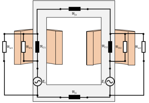
The best way to analyze such conditions is converting it to equivalent circuits (well described in another answer). To illustrate even further, this picture may help you: enter image description here

There you can see that the magnetomotive force (sources) will drive some magnetic flux to circulate, however, the magnetic flux does depend on the reluctances (defined by the medium [core, air, oil, whatever]). Thus, the presence of the core is not only magnifying the \$B\$, but conducing it and preventing it to be shared with parallel reluctances (as the air duct between coil and core). At the end, some very small flux will flow through the air duct, but it will be smaller than if the core wasn't there.

If you want to check further, a method to solve this circuit is described here, from page 77 to 80.

By the way, just to mention: in practice, this transformer with non-concentric coils doesn't work properly when some load is applied to the secondary due to the very high dispersion (too high impedance).

\$\endgroup\$
2
\$\begingroup\$

The permeability of a magnetic core might be a thousand times more than air hence, the core's "reluctance" to "conduct" magnetism is 2000 times smaller than that of air. In other words it's equivalent to a very low resistance in a regular electrical circuit (think of ohm's law).

Air (on the other hand) is like a high value resistor in parallel with a low value resistor (representing the core) in an electrical circuit. If you apply a voltage, most of the current flows through the low value resistor.

You can think of this analogy like this: -

  • Voltage applied is equivalent to the H-field
  • Resistance is equivalent to magnetic reluctance
  • Current flow is equivalent to magnetic flux density

Hence, most of the magnetism produced by the primary is coupled to the secondary.

\$\endgroup\$
3
  • \$\begingroup\$ So is the description in the question incorrect, where B is proportional to H, and H is smaller in the secondary than primary (H created from the primary side)? As for as I know, B is just H multiplied by permeability? Does B need to flow along a path similar to current? In KCL, the current along a closed path must be constant, I don't think the same restriction applies to B fields? \$\endgroup\$ Commented Mar 12 at 9:11
  • \$\begingroup\$ @JonathanLee H will be weaker in the secondary by a small amount. B and H are proportional i.e. \$B = \mu_e\cdot H\$. B isn't something that I would say flows (other than in my analogy). \$\endgroup\$
    – Andy aka
    Commented Mar 12 at 10:21
  • 1
    \$\begingroup\$ I don't think the same restriction applies to B fields <-- you can use the concept of a parallel resistor representing air's reluctance and that will satisfy the equivalent Kirchhoff law @JonathanLee \$\endgroup\$
    – Andy aka
    Commented Mar 12 at 11:46
1
\$\begingroup\$

I assume you are referring to the pair of coils with no common core of magnetic material, as shown in your top diagram.

how is it said that most of the flux density in the primary is also shared with the secondary?
It isn't. To have the two coils share the same magnetic flux, you'd have to wind them around a common "air core":

enter image description here

\$\endgroup\$
4
  • \$\begingroup\$ Try drilling a hole into the core on the secondary of a transformer, insert a H-field probe and measure the flux density. Repeat on the primary. \$\endgroup\$
    – winny
    Commented Mar 12 at 8:58
  • \$\begingroup\$ @winny This answer pertains to an air core. It's not difficult to 'try' to drill a hole through air. \$\endgroup\$
    – HarryH
    Commented Mar 14 at 7:06
  • \$\begingroup\$ @HarryH OP asked about a regular transformer with core. \$\endgroup\$
    – winny
    Commented Mar 14 at 8:05
  • \$\begingroup\$ @winny Yes, I know, but your comment (which I replied to) was to an answer which dealt specifically with an air core. \$\endgroup\$
    – HarryH
    Commented Mar 14 at 10:54

Your Answer

By clicking “Post Your Answer”, you agree to our terms of service and acknowledge you have read our privacy policy.

Not the answer you're looking for? Browse other questions tagged or ask your own question.