0
\$\begingroup\$

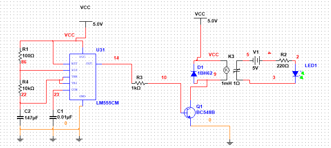
I seem to be experiencing errors when trying to toggle the relay using a 555 timer. I have used two different simulation software packages already. 

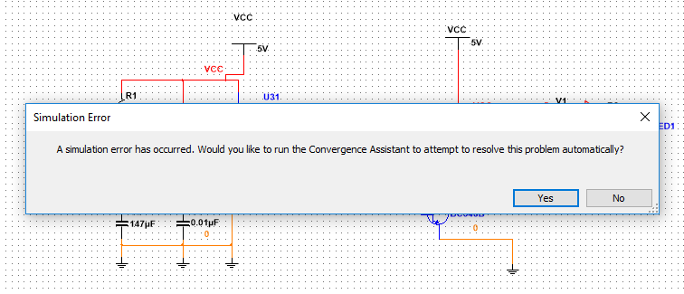
They both seem to crash. There appears to be some kind of error with convergence and time step, or something.

I was wondering if my circuit configuration is correct or how I might improve the schematic to allow it to accomplish my intended purpose?

enter image description here

It seems to work initially but then after a few seconds, the following error appears on the screen: enter image description here
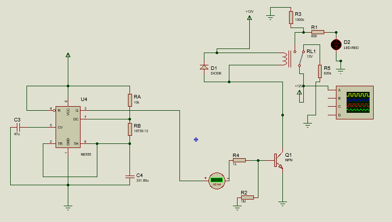
For the proteus simulation, the error only arises when I place the LED in the circuit. The schematic is as follows: enter image description here
\$\endgroup\$
4
  • 3
    \$\begingroup\$ Your floating circuit -- V1, R2, LED1 -- probably needs some sort of connection to ground, even if it's just a 1 Gohm resistor. \$\endgroup\$
    – Dave Tweed
    Commented Mar 14 at 11:06
  • \$\begingroup\$ At which point should I put it? Point 5 or point 3? \$\endgroup\$ Commented Mar 14 at 11:12
  • \$\begingroup\$ Wow. Thanks. It seems to work now! I place ground at point 5. Yeah, I think I just left some stuff floating. That was the issue. Thank you so much. \$\endgroup\$ Commented Mar 14 at 11:14
  • 1
    \$\begingroup\$ you're missing decoupling caps on the 555 chip. If this is really an LM555 or NE555, note that 5V is dangerously close to the minimum supply voltage, and it would be smarter to drive it from a higher supply voltage; or to replace it with a CMOS 555, or simply a modern microcontroller. \$\endgroup\$ Commented Mar 14 at 11:57

0

Your Answer

By clicking “Post Your Answer”, you agree to our terms of service and acknowledge you have read our privacy policy.

Browse other questions tagged or ask your own question.