-2
\$\begingroup\$

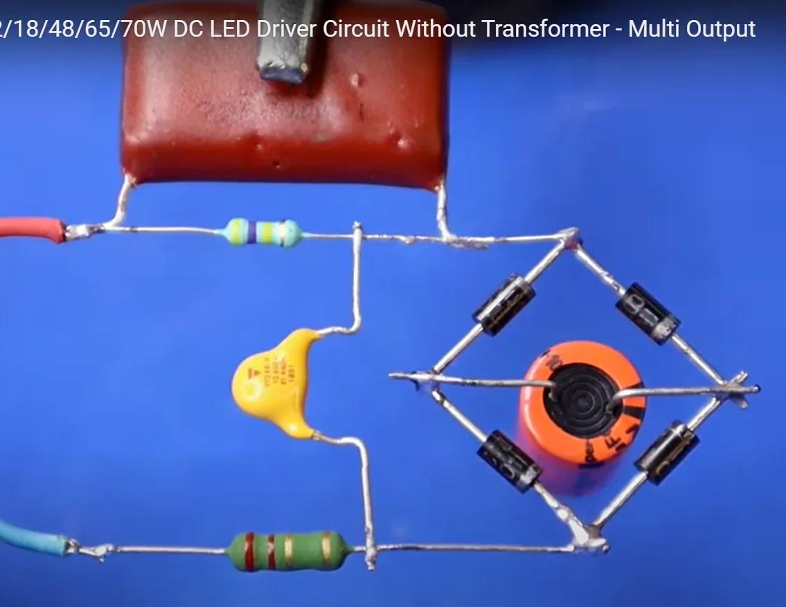
In a video on YouTube I saw a simple LED driver circuit. This circuit is quite different from the circuits that I have learned during my studies like boost converter, buck converter, buckboost converter etc.

As far as I can see most LED driver circuits are a form of this one below. Could someone please point me to some textbook (or a video / tutorial) with good explanation on how this works theoretically? I would like to be able to understand the internal workings and how the other variations of this circuit as well. Does this circuit setup have a name?

enter image description here https://www.youtube.com/watch?v=XFwBsyDIZrc

\$\endgroup\$
3
  • 1
    \$\begingroup\$ A circuit like the one in the video can potentially kill someone. \$\endgroup\$ Commented Mar 24 at 22:48
  • \$\begingroup\$ You can look up capacitive dropper to find out how that specific circuit works, although it is not all that common outside of very cheap products. Arguably much more common would be a dedicated constant current driver IC. \$\endgroup\$ Commented Mar 24 at 22:48
  • \$\begingroup\$ I don't see an LED in your picture. \$\endgroup\$
    – Andy aka
    Commented Mar 25 at 8:42

1 Answer 1

1
\$\begingroup\$

What you've found is a simple transformerless power supply. It is also known as a capacitive dropper.

The way it works is that it uses the impedance of the series capacitor (the big red capacitor marked 225 for 2.2uF) to limit the current.

A 2.2 uF capacitor has an impedance of about 1445 ohms at 50Hz. At 220VAC, that's a current of about 150 milliamperes. If you short circuit the DC output, it will only draw 150mA from the AC side. The DC current would be around 200mA.

The circuit is an approximation of a constant current source. It has a fairly high input voltage in series with a (relatively) high impedance.

It isn't really a good current source, however. The output current varies with the input voltage and with the load.


If you use such a circuit, you must make sure that it is completely insulated. The supposed low voltage side is connected directly to the mains. Touching the output can kill you just as easily as touching the mains on the input side.


Contrary to what other folks have found, I have found such cheap circuits in brand name 220V LED bulbs.

Here's the circuit from a bulb I disassembled a few years ago:

enter image description here

The circuit doesn't work well. The bulb quit working a few months after I bought it.
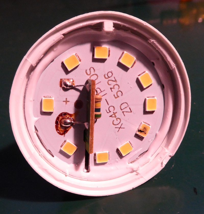
enter image description here

One of the LEDs in the bulb is damaged. Whether from too much current all the time or because the circuit let through a high voltage (and higher current) surge I couldn't say.

The inductor is a half-hearted attempt at preventing high voltage spikes from getting to the LEDs. I doubt it really does much.

R1 is to discharge C1 when the bulb is disconnected from AC. Likewise, R2 is to discharge C2.

\$\endgroup\$
3
  • \$\begingroup\$ I was looking at some of my own early LED lamps and some recently purchased ones. The older circuits are more sophisticated. And today they overdrive them as, I believe, they pretty much want them to be cheap, bright when cheap, and to fail sooner. However, it appears that Dubai made a special deal with Philips. Those we often find when not in Dubai may be made to last longer when modified. \$\endgroup\$ Commented Mar 25 at 4:52
  • \$\begingroup\$ In that case, is it also correct that in the simple case that I provided the current going through the LEDs will not be the same when we compare let's say 2 LEDs vs 20 LEDs in series? The voltage drop per LED is constant, so if you have more LEDs you will have a higher voltage drop, which means less voltage drop is left for the capacitor, which on its turn means less current flowing through the capacitor (C * dV/dt) and thus the rest of the circuit. Am I thinking in the correct way and direction? \$\endgroup\$
    – MasterMind
    Commented Mar 25 at 11:24
  • \$\begingroup\$ Could you also explain the use of L1, R1 and R2 in the circuit. What purpose do they serve in general in circuits like these? \$\endgroup\$
    – MasterMind
    Commented Mar 25 at 11:26

Not the answer you're looking for? Browse other questions tagged or ask your own question.