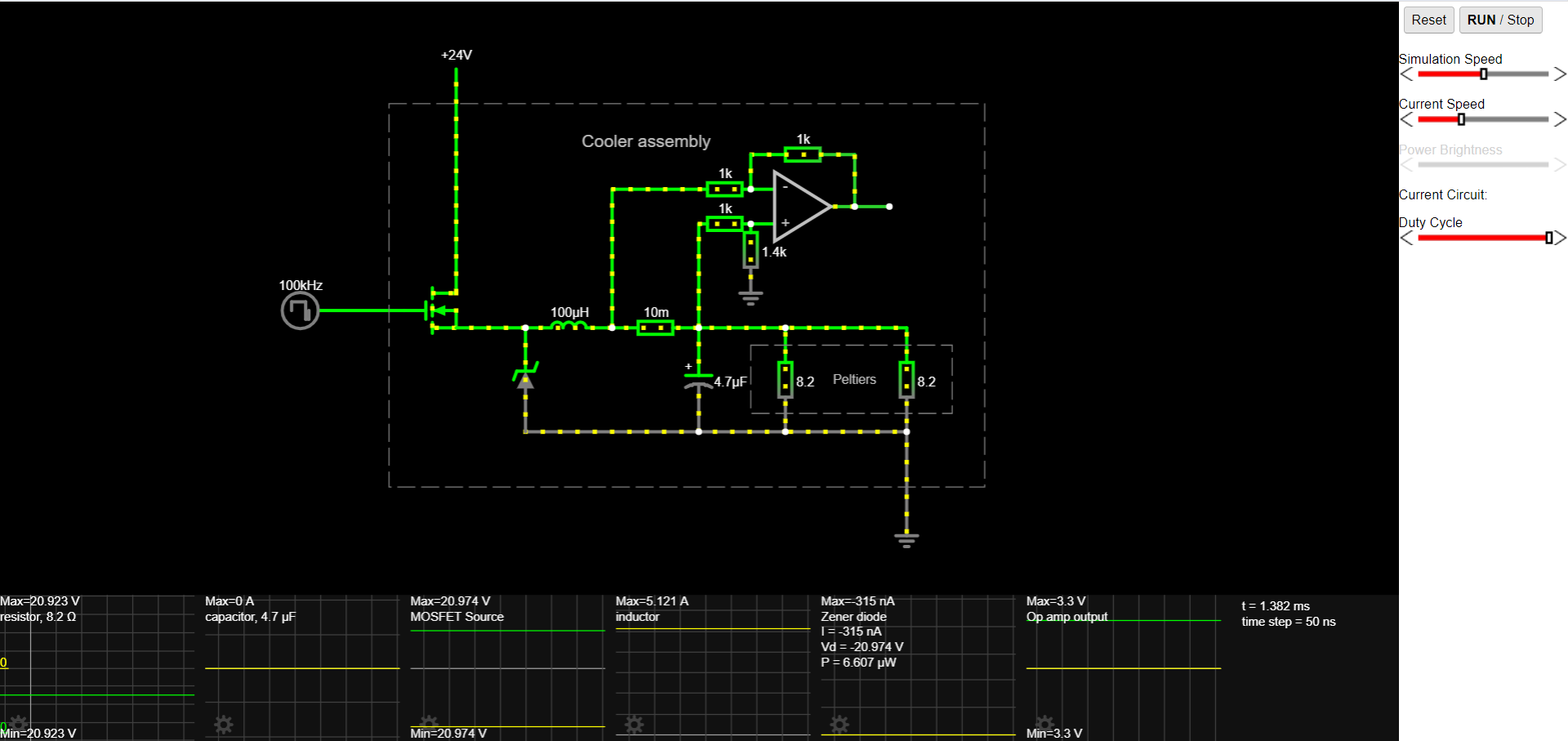
I am building a digitally controlled constant current switching power supply. This circuit will deliver no more than 105 Watts at around 20V from an AC-DC DIN rail SMPS of 250W.
You can see and operate the circuit in falstad
Here is a screenshot of it at maximum power delivery when duty cycle is at 100%:
The worst case scenario is if the MOSFET gate signal starts at 100% duty cycle. The capacitor will start charging rapidly and current through the inductor and MOSFET will increase continuously until the capacitor is fully charged. Since this is a digitally controlled system, I want to make sure that the components are safe even if the software bugs out.
The approach I took is downsizing the capacitor to 4.7uF which in simulation gives a good amount of ripple at the output for the application and a peak charge current of 6A. I will be using a 7A inductor as when the regulator is at full power it will supply 5 Amps. The inductor is the bottleneck setting the maximum current through the regulator to 7A max.
I see that the appropriate solution is an NTC thermistor and found the EPCOS B57237S0259M000 to be the appropriate candidate.
My question is: Given that the regulator will be powered by an AC-DC SMPS, can I rely on the SMPS' overcurrent protection?
And my guess is: No. Because the SMPS overcurrent protection might trigger at a current way over my components' rated spec (7 Amps, the inductor's rating).
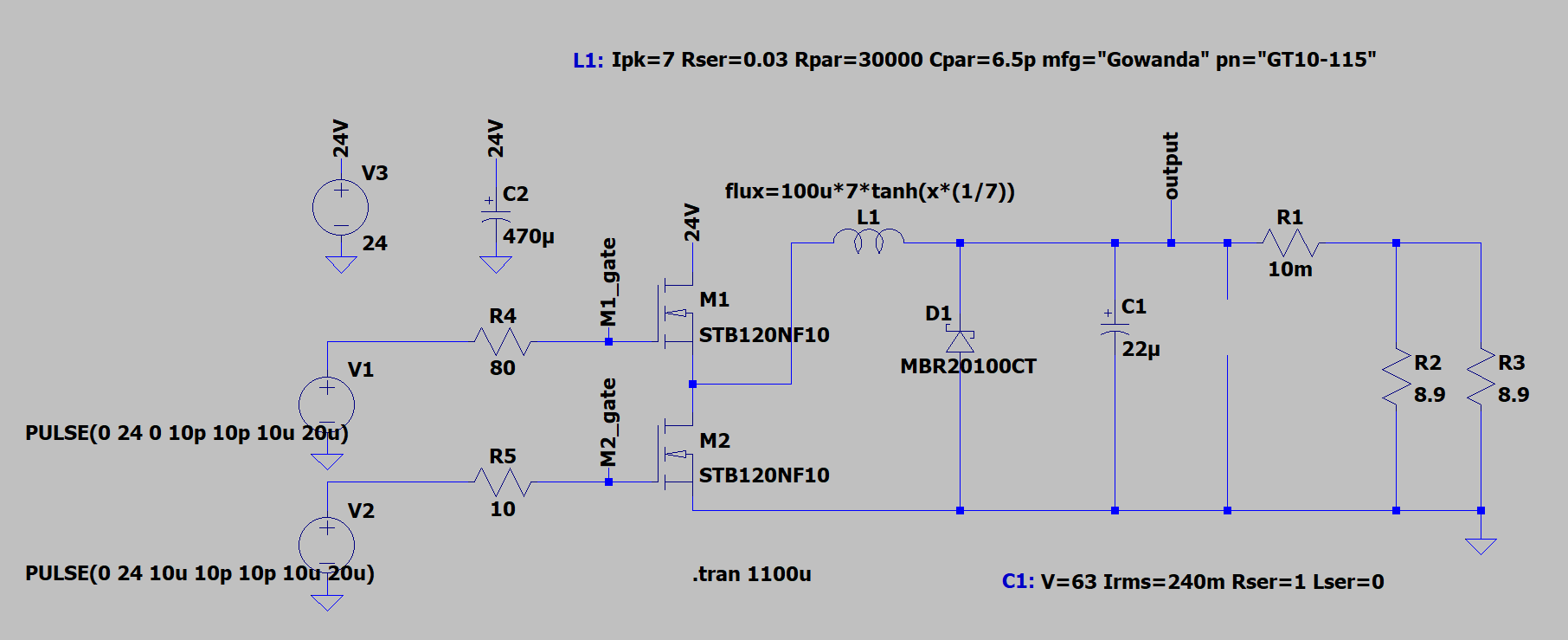
Edit: Thank you for your valuable comments. I have now moved on to a synchronous configuration that I am simulating in LTSpice:
And I am using two SI8261 isolated drivers fed complementary PWM signals to drive the gates of the MOSFETs (not pictured in Spice). These specify they must have a >1uF decoupling capacitor between VDD (24V) and GND so I added a 10uF.
D1 prevents C1 from being under reverse voltage - clamping to about -600mV. This condition may arise from ringing triggered by M2 conducting for a too long period of time after C1 has been fully charged. ie: Going from 90% to 10% duty cycle (which I will prevent via current control).
I have prepared a prototype in hardware and ran some tests on the gate drivers until I was satisfied with dead-time and the waveform at the gates before adding the MOSFETs, L1 inductor, D1 schottky and C1 capacitor.
I have ran a test at 20% duty cycle using a current-limited bench power supply and DC load. This was without the C2 470uF decoupling capacitor, which was a mistake. Although appropriately rated, the 10uF capacitor started smoking slowly. I did see this but did not stop the test right away as I wanted to probe it and the current draw was rather meager at 200mA 24V from the bench supply. I could catch the 24V supply going negative for a short amount of time on my scope before the capacitor quietly blew. At the moment of testing only this 10uF decoupling the drivers was in the circuit. This leads me to think it was not nearly large enough to stabilize the supply voltage.
This edit does not relate so much to current protection, however there are some other issues to work through first. I wanted to update so you can see this question is not stale. In simulation I can see the two possible worst case scenarios being (1) M1 off, M2 on and capacitor charged (low resistance path to ground through the inductor) and (2) M1 on, M2 off and capacitor discharged (high capacitor charge current spike).
My next steps will be to fix the prototype, add C2, replace one of the drivers and repeat the test by setting the current limit lower and slowly increasing voltage.
See my replies to comments for more context.


