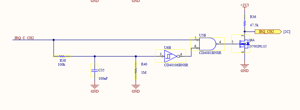
I stumbled upon this part of the schematic (page 2) of the Arduino Portenta Edge Control (shown below), which – in my eyes — seems to be a debounce circuit, but more complex than the one shown in this TI video.
It uses an inverting Schmitt Trigger, which is fed into an AND gate, which in turn controls an N-Channel MOSFET.
As I understand, the truth table for the AND Gate would be:
| IRQ_C_CHn | AND Input 1 | AND Input 2 (Schmitt output) | AND Output |
|---|---|---|---|
| LOW | LOW | HIGH | LOW |
| HIGH | HIGH | LOW | LOW |
For me, it seems unlikely that the AND-Gate output would experience a state change, so how does this circuit works?
As a bonus question: what are its advantages over a classic RC + Schmitt-Trigger circuit?

