1
\$\begingroup\$

I am trying to reverse engineer a constant power laser driver. Unlike constant current drivers, these use an integrated photodiode which monitors the laser diode output. The photodiode current feeds back into the driving amplifier to improve stability.

As someone with experience mostly with digital electronics, I find the dual stage amplifier and voltage references to be confusing. From what I have gathered, the 33 uF capacitor slowly charges and provides a gentle startup for the diode. R9 and the LM336 Zener diode establish a 2.5 V reference voltage. The trimmer pot creates a voltage divider to adjust this reference voltage entering the non-inverting input of the opamp first stage.

I am unsure how to calculate the gain of the first stage since the feedback network has a resistor to ground. Are R7/R8/C4 an RC filter plus a pull-down? Why is there another Zener diode D1 between the first stage output and second stage non-inverting input? How can I calculate the second stage gain given R10 and R_FEEDBACK which can be adjusted from 690 Ω to 249 kΩ? How might I figure out the values of C2/C4/C5/C6 as they are unmarked 0603 capacitors?

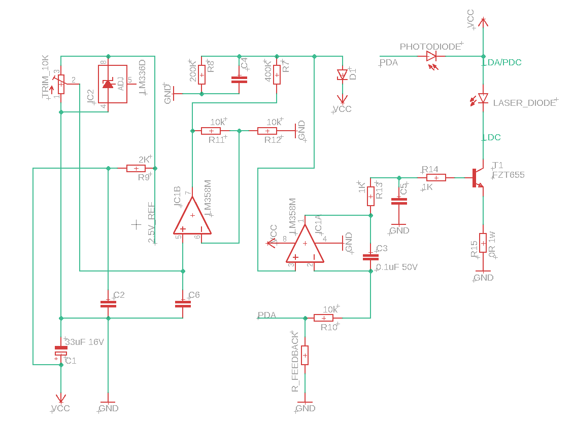
laser driver circuit

\$\endgroup\$
7
  • \$\begingroup\$ “How might I figure out the values of C2/C4/C5/C6 as they are unmarked 0603 capacitors?” Unsolder and measure. \$\endgroup\$
    – winny
    Commented Apr 5 at 15:23
  • 1
    \$\begingroup\$ The schematic seems to have been laid out by a sadist, perhaps to discourage understanding. Let's have the signal flow going left to right, +ve voltages to the top, all labels the same way up, please. I'll come back and have a look at the circuit when those changes have been made. \$\endgroup\$
    – Neil_UK
    Commented Apr 5 at 15:45
  • \$\begingroup\$ There seems to be mistakes in this poorly presented schematic. Do you have a source for this circuit? \$\endgroup\$
    – MOSFET
    Commented Apr 5 at 15:46
  • 1
    \$\begingroup\$ Something as those mouser.com/pdfDocs/DrivingCircuitExamplesofLaserDiodes.pdf \$\endgroup\$
    – Antonio51
    Commented Apr 5 at 16:22
  • \$\begingroup\$ Selene, is the drawing under your control now because, if it is there are a number of improvements that will make it much clearer. \$\endgroup\$
    – Andy aka
    Commented Apr 5 at 17:44

1 Answer 1

0
\$\begingroup\$

I am unsure how to calculate the gain of the first stage since the feedback network has a resistor to ground.

This stage amplifies the voltage at the wiper of the potentiometer (10 kΩ) by 2. That's the voltage that comes out of IC1B.

Are R7/R8/C4 an RC filter plus a pull-down?

R7 and R8 form a potential divider reducing the output of IC1B by 3 and, C4 adds some low-pass filtering to that divided signal.

Why is there another Zener diode D1 between the first stage output and second stage non-inverting input?

I don't think that is meant to be a Zener diode. Anyway, when power to the circuit is removed, D1 discharges capacitor C4.

How can I calculate the second stage gain given R10 and R_FEEDBACK which can be adjusted from 690 Ω to 249 kΩ?

Here's where you need to rethink how you look at this. It's an integrator and has a massive (and largely irrelevant) DC gain that ensures that the light output of the photodiode produces a photocurrent that creates a voltage at node PDA that matches the voltage coming from the junction of C4 and D1. It's a control loop and it's unhelpful to think of it having a specific gain value.

How might I figure out the values of C2/C4/C5/C6 as they are unmarked 0603 capacitors?

  • C2 connects between Vcc and GND so anything from 100 nF to 10 uF will work here
  • C4 slows down demand changes from IC1B so, it might be anywhere from 1 nF to 10 μF. I suggest you start with 100 nF
  • C5 (and R13) form a low-pass filter that slows down the control loop around IC1A and, it could go unstable with a value that is too high so, I'd begin with 100 pF
  • C6 connects the demand pot wiper to GND just to provide a smoother control. I expect 100 nF will be fine
\$\endgroup\$
1
  • \$\begingroup\$ Thank you so much Andy this makes everything so much clearer! \$\endgroup\$ Commented Apr 11 at 20:03

Your Answer

By clicking “Post Your Answer”, you agree to our terms of service and acknowledge you have read our privacy policy.

Not the answer you're looking for? Browse other questions tagged or ask your own question.