I need to drop voltage for unipolar stepper motor with winding resistance 50ohm and inductance 40mH (measured with generator and oscilloscope for equivalent circuit Rout + (Rl + L)). Available Vcc is 24V or 5V, motor at 5V has weak torsion and speed, at 24V chopping and getting warm. Good range is 10-16V when motion is smooth, fast and strong.
I tested plenty of options and only feasible apparently seems option mentioned in Practical examples of http://homepage.divms.uiowa.edu/~jones/step/current.html. Main points: high side sensing as sensing resistor must be in decay loop (which is not at low side). Opamp/comparator must work around Vcc, which is very rare but TLV1701 is available in Farnel and satisfies condition. Hi-side P-MOSFET on is not an option because of position of sensing resistor vs. Vref (i.e. AND gates).
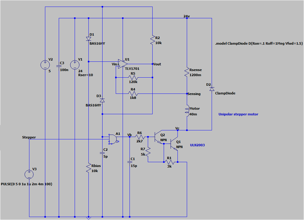
Circuit is non-inverting comparator with hysteresis. Vh relates to high voltage at sensing resistor, i.e. low current. Vl related to low voltage when current flows and causes voltage drop.
Supposed current range 0.29A-0.2A which corresponds to 23.71-23.8V Vsense, Vref (Vin-) 23.45V. Leeds to cirtuit:
Simulation in LTSpice VII looks great: exponentially raising current, power dissipation is reasonable, current max.value is slightly higher than used for component calculation.
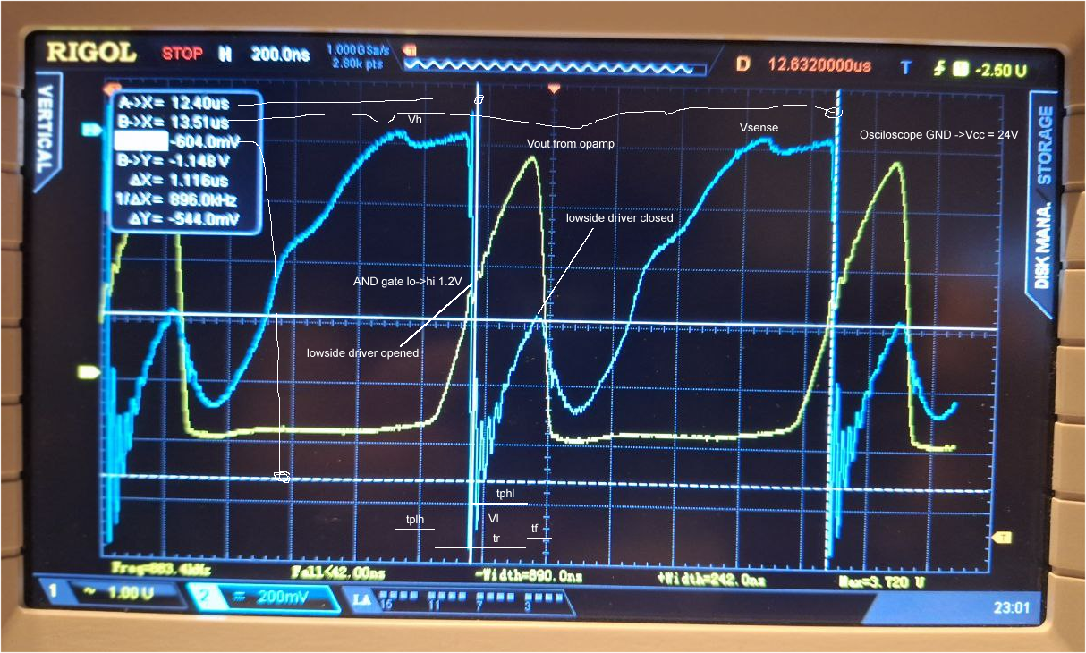
But in reality I saw Vcc flowing from 20V to 27V, strange random switching around 1MHz. LTSpice it supposed in kHz. PSU powering circuit is adapter 24V/2A. I don't understand what causes oveshooting, likely switching power supply does not like voltage rice when inductor decays through clamp diode, Vcc rises and PSU is somehow compensates. I believe sinus voltage is not good for comparator event inputs are relative to Vcc and high precision is not required. So I added non-ESR capacitor 220uF to Vcc near motor. Vcc became smooth. But LTSpice simulation is not as good as was.
What is wrong is real behavior. There are two major differences, switching frequency and mainly current seems more as capacitive load. When switched on (low coil side is connected to GND) then rises and likely causes immediate switch off. Here plays main role likely comparator deleys, not hysteresis levels. Motor is strong and smooth but issue is overheating of ULN2003 driver. Probably because of overshooting current (604mV cca 0.5A, not so bad), but mean current value should be much lower. I believe bipolar transitors must go immediately to saturation (there is sharp edge at AND gate output and darlington in driver) so resistance should be low.
 Note: oscilloscope probe GND to Vcc to see nearby Rsense voltage without DC. So 0V on cyan graph is null current, -120mV is 100mA.
Can you see what is not considered in circuit model that real result is completely different? Mainly:
- switching frequency
- opposite current graph
- driver dissipation
Maybe motor is moving so it is also generator on non-active windings ?
Anyway is it feasible somehow via PWM? I tried superpose 10-20kHz PWM signal to open collector output from comparator. Duty up to 80% was ok in terms of motor torsion/speed but still dissipation was high. I could not keep finger on chip after 10-15secs.
Currently only reliable solution seems extra switching PSU 24V->15V. Drawback is price and mainly I have not enough space for relatively large driver+schottky+inductor+bulk capacitors. BTW does not exist trick how to reuse motor coils in switching circuit instead of low-resistance coil dedicated to buck driver?
Related original question: Low side driver for unipolar stepper motor (voltage drop or current limiter) for-unipolar-stepper-motor-voltage-drop-or-current-limiter


