Some of the answers are now incorrect because the original question was "confused". In an ideal world, the question should have been maintained with its original sense after answers were given. Due to the very substantial "churn", I have decided to edit it and reopen it with the OP's intended meaning. The aggravation caused to various members is regretted. || RM (moderator)
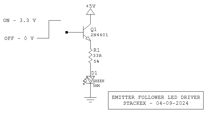
I wish to use a GPIO pin to drive an LED, but the GPIO current capabilities are too low. In addition,
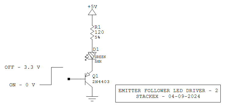
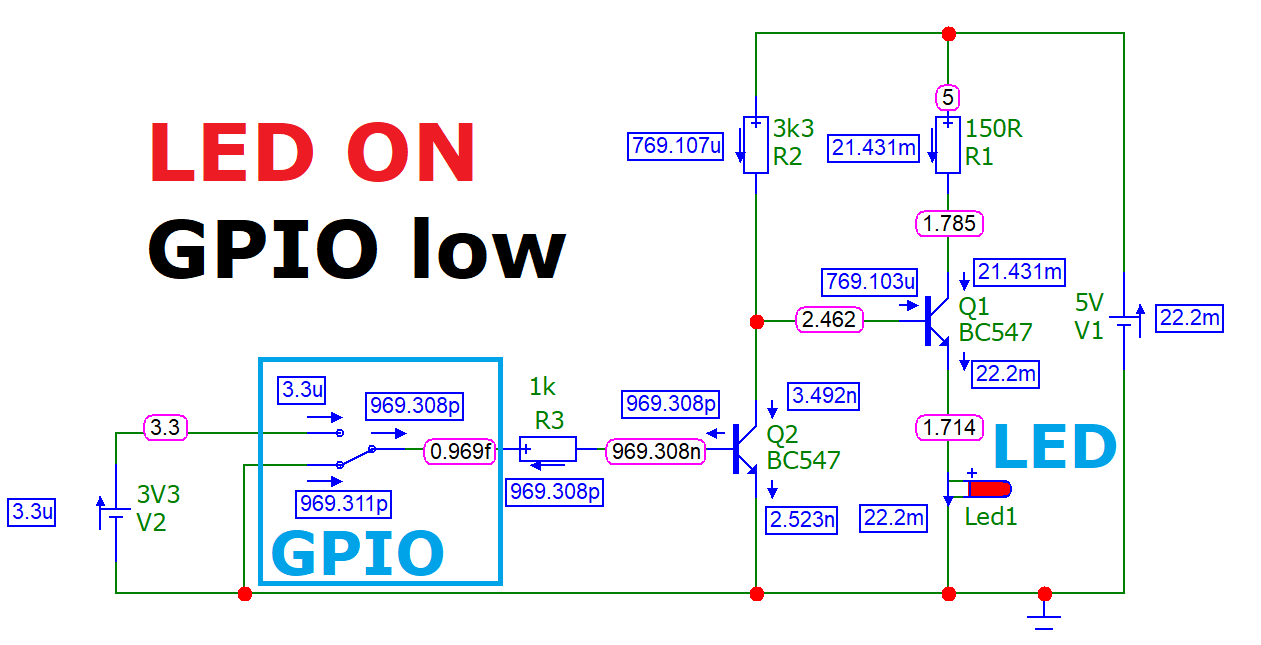
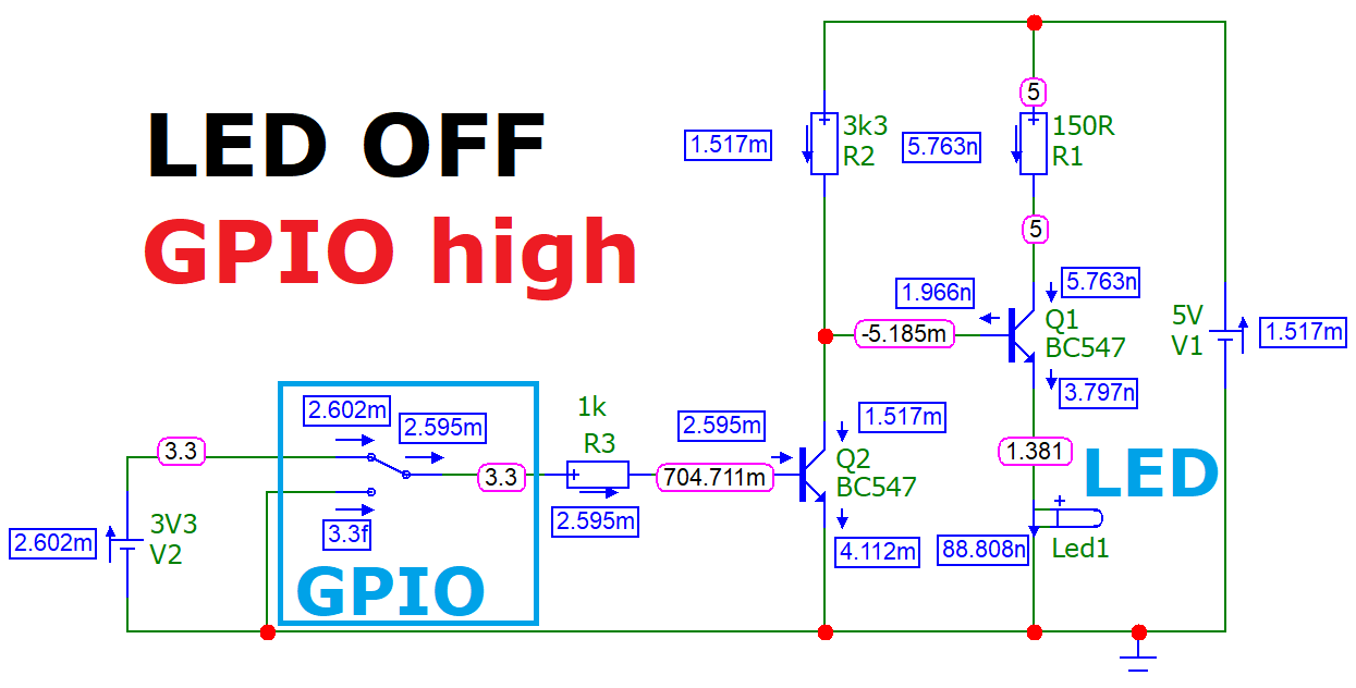
The LED is expected to light when the GPIO output signal is low.
The GPIO has a +3.3 V supply and is a LVTTL output
I want to power the LED using a +5 V source.
The current GPIO is rated @ 5 mA maximum, and
The LED will be driven with 10 mA initially.
I assume that characteristics of GPIO may change with processor board change. The LED I am going to use typically has a nominal 2 V drop at 20 mA.
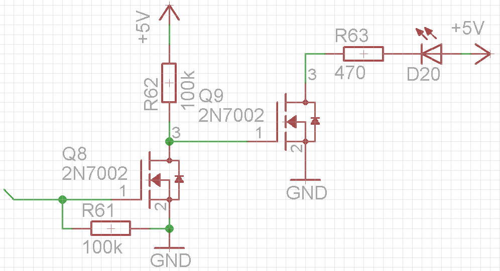
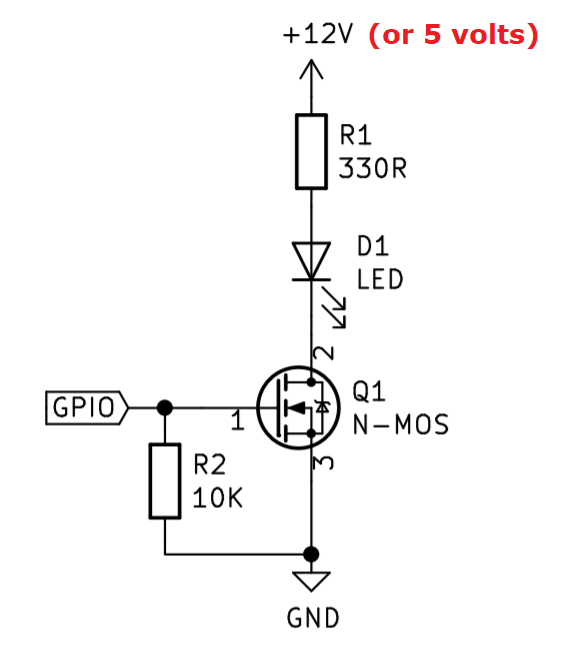
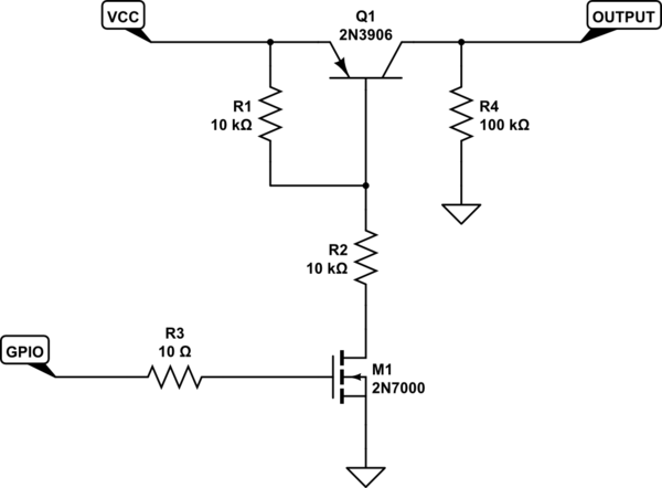
Initially I designed a simple driver using FET and gate pull-down resistor, but then realized that for some pins I will not be able to change polarity of the active signal in the firmware. As my above described single FET based circuit is inverting it would not light the LED when the GPIO was low, as is required.
I looked through the web to find some complicated circuits, but I need a simple and cost-effective solution performing its duties and not firing current back from 5 V to 3.3 V.
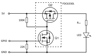
I'd probably try two FETs daisy chained, but is it the best way to go, and are there two FETs in single package (or even more FETs, as I have several LEDs to drive)?
Any ideas? Thanks!
Regarding the term "inverting", let me clarify: if you consider two situations: LED pulled up to Vcc, and LED pulled up to Vcc through FET, you will have LED lighting when input is low in first case, and not lighting in second case. The discussion is not about currents and voltages, it about the state of the LED. This was my mistake not clarifying that originally signal polarity is negative - in other words the LED is expected to light when the signal is low.
Does this one look appropriate? The only issue remaining is to choose the transistor, what's about IRLML2803?
Found the device NDC7002N, old one, but seemingly to fit the requirements: threshold is appropriate for 3.3V-LVTTL switching. Relatively high Rdson is no problem here as series resistors are high enough to have fraction of power through the transistor.
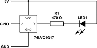
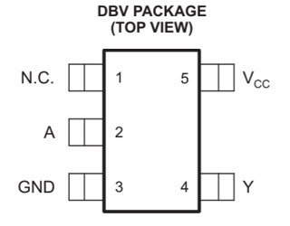
Update: I have chosen to use 1G17, and it works as expected. The main thing here is you must use genuine (e.g. TI) chips with partial-power-down capability as other manufacturers may not have it. Check datasheets carefully.

